TRANSAXLE FLUID TEMPERATURE (TFT) SENSOR REMOVAL/INSTALLATION [FS5A-EL]
id051721801100
-
Warning
-
• A hot transaxle and ATF can cause severe burns. Turn off the engine and wait until they are cool.
• Using compressed air can cause dirt and other particles to fly out, causing injury to the eyes. Wear protective eyeglasses whenever using compressed air.
-
Caution
-
• Water or foreign objects entering the connector can cause a poor connection or corrosion. Be sure not to drop water or foreign objects on the connector when disconnecting it.
1. Remove the primary control valve body.
- (1) Disconnect the negative battery cable.
- (2) Remove the aerodynamic under cover NO.2. (SeeAERODYNAMIC UNDER COVER NO.2 REMOVAL/INSTALLATION.)
- (3) Clean the transaxle exterior throughout with a steam cleaner or cleaning solvents.
- (4) Drain the ATF into a separate suitable container. (See AUTOMATIC TRANSAXLE FLUID (ATF) REPLACEMENT [FS5A-EL].)
- (5) Remove the air cleaner component. (See INTAKE-AIR SYSTEM REMOVAL/INSTALLATION [MZR 1.8, MZR 2.0, MZR 2.5].) (See INTAKE-AIR SYSTEM REMOVAL/INSTALLATION [MZR 2.0 DISI].)
- (6) Remove the front crossmember. (See FRONT CROSSMEMBER REMOVAL/INSTALLATION.)
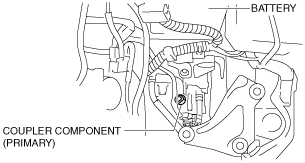
- (7) Disconnect the coupler component connector (primary).
-
- (8) Remove the oil pan. (See PRIMARY CONTROL VALVE BODY REMOVAL [FS5A-EL].)
- (9) Remove the primary control valve body. (See PRIMARY CONTROL VALVE BODY REMOVAL [FS5A-EL].)
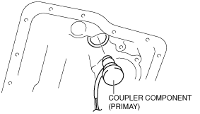
- (10) Remove the coupler component (primary) from transaxle case.
-
- (11) Remove the O-ring from the coupler component (primary).
2. Install the primary control valve body.
- (1) Apply ATF to a new O-ring and install it on the coupler component (primary).
- (2) Install the coupler component (primary) to transaxle case.
- (3) Install the primary control valve body. (See PRIMARY CONTROL VALVE BODY INSTALLATION [FS5A-EL].)
-
-
Caution
-
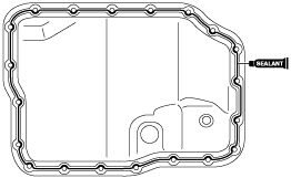
• If any old sealant gets into the transaxle during installation of the oil pan, trouble may occur in the transaxle case and oil pan, and clean with cleaning fluids.
- (4) Apply a light coat of silicon sealant (TB1217E) to the contact surfaces of the oil pan and transaxle case.
-
3. Install the oil pan before the applied sealant starts to harden.
-
Caution
-
• The removed bolts with spring washer cannot be reused. If they are reused, it could loosen the bolts due to spring weakness.
-
Tightening torque
-
Flange bolt: 6.0—8.0 N·m {62—81 kgf·cm, 54—70 in·lbf}
Bolt with spring washer: 8—10 N·m {82—101 kgf·cm, 71—88 in·lbf}
4. Install the front crossmember. (See FRONT CROSSMEMBER REMOVAL/INSTALLATION.)
5. Install the air cleaner component. (See INTAKE-AIR SYSTEM REMOVAL/INSTALLATION [MZR 1.8, MZR 2.0, MZR 2.5].) (See INTAKE-AIR SYSTEM REMOVAL/INSTALLATION [MZR 2.0 DISI].)
6. Add the ATF. (See AUTOMATIC TRANSAXLE FLUID (ATF) REPLACEMENT [FS5A-EL].)
7. Connect the coupler component connector (primary).
8. Install the aerodynamic under cover NO.2. (SeeAERODYNAMIC UNDER COVER NO.2 REMOVAL/INSTALLATION.)
9. Connect the negative battery cable.
10. Perform the “Mechanical System Test“. (See MECHANICAL SYSTEM TEST [FS5A-EL].)