 |
am6zzw00004886
SOLENOID VALVE REMOVAL/INSTALLATION (PRIMARY CONTROL VALVE BODY) [FS5A-EL]
id051721807800
1. Disconnect the negative battery cable.
2. Remove the aerodynamic under cover NO.2. (See AERODYNAMIC UNDER COVER NO.2 REMOVAL/INSTALLATION.)
3. Clean the transaxle exterior throughout with a steam cleaner or cleaning solvents.
4. Drain the ATF into a separate suitable container. (See AUTOMATIC TRANSAXLE FLUID (ATF) REPLACEMENT [FS5A-EL].)
5. Remove the front crossmember. (See FRONT CROSSMEMBER REMOVAL/INSTALLATION.)
6. Remove the oil pan. (See PRIMARY CONTROL VALVE BODY REMOVAL [FS5A-EL].)
7. Remove the primary control valve body. (See PRIMARY CONTROL VALVE BODY REMOVAL [FS5A-EL].)
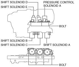
8. Remove the solenoid valve (s).
am6zzw00004886
|
9. Apply ATF to a new O-ring and install it on the solenoid valve.
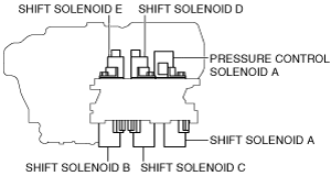
10. Install the solenoid valve in the primary control valve body.
am6zzw00004897
|
11. Install the primary control valve body. (SeePRIMARY CONTROL VALVE BODY INSTALLATION [FS5A-EL].)
12. Install the oil pan. (SeePRIMARY CONTROL VALVE BODY INSTALLATION [FS5A-EL].)
13. Install the front crossmember. (SeeFRONT CROSSMEMBER REMOVAL/INSTALLATION.)
14. Add the ATF. (SeeAUTOMATIC TRANSAXLE FLUID (ATF) REPLACEMENT [FS5A-EL].)
15. Install the aerodynamic under cover NO.2. (SeeAERODYNAMIC UNDER COVER NO.2 REMOVAL/INSTALLATION.)
16. Connect the negative battery cable.
17. Perform the “Mechanical System Test“. (SeeMECHANICAL SYSTEM TEST [FS5A-EL].)
18. Perform the “Road Test“. (See ROAD TEST [FS5A-EL].)