 |
am6xuw00011442
REAR UPPER ARM REMOVAL/INSTALLATION [4WD]
id0214008008a2
1. Switch the ignition ON (engine off).
2. Release the electric parking brake.
3. Switch the ignition off.
4. Disconnect the negative battery terminal. (See NEGATIVE BATTERY TERMINAL DISCONNECTION/CONNECTION.)
5. Remove the wheels and tires. (See WHEEL AND TIRE REMOVAL/INSTALLATION.)
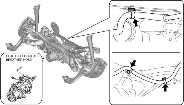
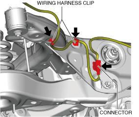
6. Disconnect the wiring harness clips and connector installed to the rear crossmember.
am6xuw00011442
|
7. Disconnect the rear differential breather hose and set it aside so that it does not interfere with the servicing. (See REAR DIFFERENTIAL REMOVAL/INSTALLATION.)
am6xuw00011443
|
8. Disconnect the rear ABS wheel-speed sensor wiring harness and the electric parking brake motor gear unit connector and set it aside so that it does not interfere with the servicing.
am6xuw00011444
|
9. Remove the following parts: (See FLOOR UNDER COVER REMOVAL/INSTALLATION.)
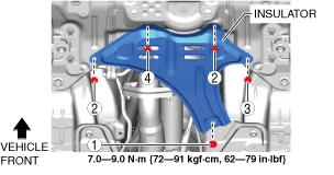
10. Remove the fasteners and bolt in the order shown in the figure.
am6xuw00011445
|
11. Remove the insulator.
12. Remove the following parts: (See EXHAUST SYSTEM REMOVAL/INSTALLATION [SKYACTIV-D 2.2].)
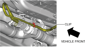
13. For SKYACTIV-D 2.2 (Without SCR system) vehicles, perform the following procedure.
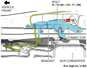
14. For SKYACTIV-D 2.2 (With SCR system) vehicles, perform the following procedure.
am6xuw00011446
|
am6zzw00017169
|
15. Remove the propeller shaft. (See PROPELLER SHAFT REMOVAL/INSTALLATION.)
16. Remove the rear coil spring. (See REAR COIL SPRING REMOVAL/INSTALLATION.)
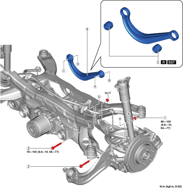
17. Remove in the order indicated in the table.
18. Install in the reverse order of removal. (See Suspension Links Installation Note.)
19. Inspect the wheel alignment and adjust it if necessary. (See REAR WHEEL ALIGNMENT.)
am6xuw00011448
|
|
1
|
Rear upper arm outer nut
(See Rear Upper Arm Removal Note.)
|
|
2
|
Rear upper arm outer bolt
(See Rear Upper Arm Removal Note.)
|
|
3
|
Rear upper arm inner bolt
(See Rear Upper Arm Removal Note.)
|
|
4
|
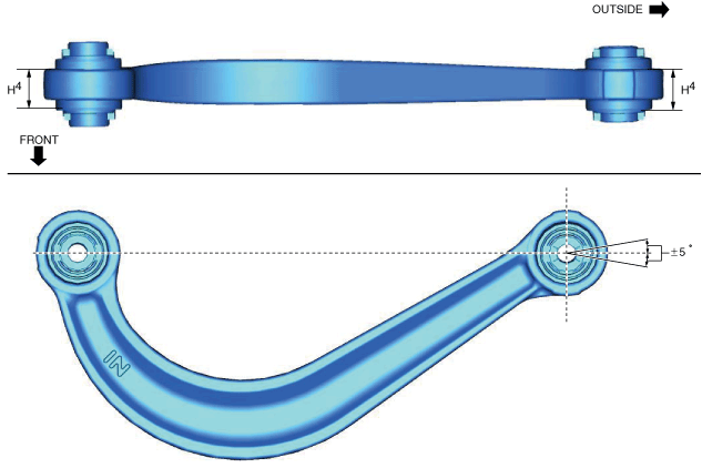
Rear upper arm
(See Rear Upper Arm Removal Note.)
|
|
5
|
Rear upper arm bushing
|
Rear Upper Arm Removal Note
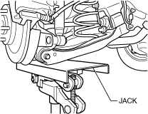
1. Jack up the vehicle to the unloaded condition, and support the rear lower arm using a jack.
ac5wzw00002859
|
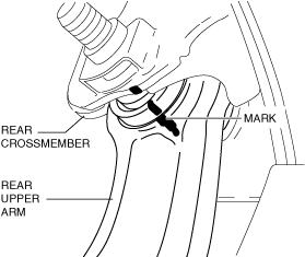
2. Align the rear crossmember component and rear upper arm and mark them.
ac5uuw00009046
|
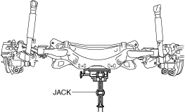
3. Support the rear crossmember component with a jack and remove the rear crossmember installation nuts.
ac5uuw00000195
|
4. Press down on the rear crossmember component slowly until the rear upper arm inside installation bolts can be removed using a jack.
ac5wzw00002326
|
5. Remove the rear upper arm.
Rear Upper Arm Bushing Removal Note
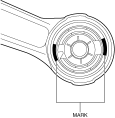
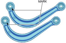
1. Mark the rear upper arm as shown in the figure.
ac5uuw00006792
|
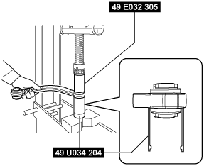
2. Press the rear upper arm bushing out using the SSTs.
ac5wzw00002155
|
Suspension Links Installation Note
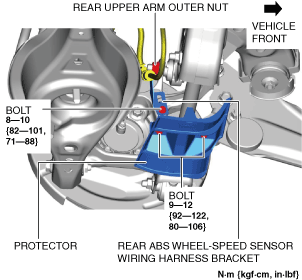
1. Remove the protector.
am6xuw00011449
|
2. Remove the rear ABS wheel-speed sensor wiring harness bracket.
3. When installing the joint sections with rubber bushings, perform the following procedures.
Rear Upper Arm Bushing Installation Note
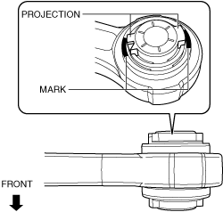
1. Mark the new rear upper arm bushing as shown in the figure.
ac5wzw00011216
|
2. Align the projection of a new rear upper arm bushing with the marks placed during removal.
ac5wzw00011217
|
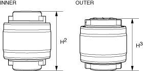
3. Press fit the rear upper arm bushing until the marks placed in Step 1 cannot be seen using the SSTs.
ac5uuw00001634
|
ac5wzw00002158
|
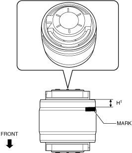
4. After installing the rear upper arm bushing, verify that it is installed to the position shown in the figure.
am6xuw00011450
|
Rear Upper Arm Inner Bolt Installation Note
am6xuw00011451
|
1. Align the alignment marks and tighten the rear upper arm inner bolt to the specified torque.
2. Lift up the rear crossmember component using a jack and install the rear crossmember installation nuts.
ac5uuw00000195
|
Rear Upper Arm Outer Bolt Installation Note
1. Insert the rear upper arm outer bolt from the front of the vehicle.