 |
am6xuw00011476
REAR STABILIZER REMOVAL [4WD]
id0214008041a2
1. Switch the ignition ON (engine off).
2. Release the electric parking brake.
3. Switch the ignition off.
4. Disconnect the negative battery terminal. (See NEGATIVE BATTERY TERMINAL DISCONNECTION/CONNECTION.)
5. Remove the wheels and tires. (See WHEEL AND TIRE REMOVAL/INSTALLATION.)
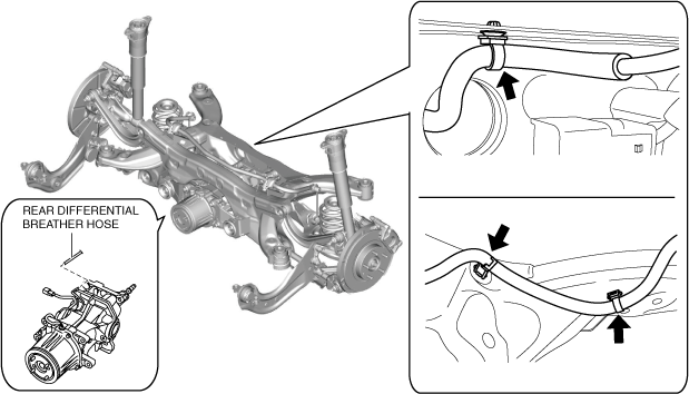
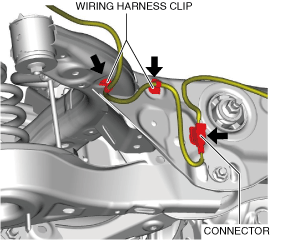
6. Disconnect the wiring harness clips and connector installed to the rear crossmember.
am6xuw00011476
|
7. Disconnect the rear differential breather hose and set it aside so that it does not interfere with the servicing. (See REAR DIFFERENTIAL REMOVAL/INSTALLATION.)
am6xuw00011477
|
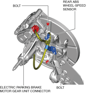
8. Disconnect the rear ABS wheel-speed sensor wiring harness and the electric parking brake motor gear unit connector and set it aside so that it does not interfere with the servicing.
am6xuw00011478
|
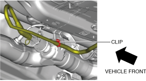
9. Remove the following parts: (See FLOOR UNDER COVER REMOVAL/INSTALLATION.)
10. Remove the fasteners and bolt in the order shown in the figure.
am6xuw00011479
|
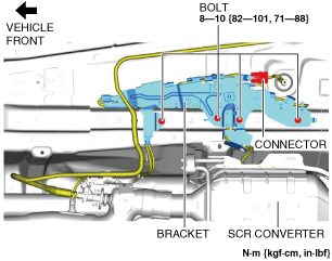
11. Remove the insulator.
12. Remove the following parts: (See EXHAUST SYSTEM REMOVAL/INSTALLATION [SKYACTIV-D 2.2].)
13. For SKYACTIV-D 2.2 (Without SCR system) vehicles, perform the following procedure.
14. For SKYACTIV-D 2.2 (With SCR system) vehicles, perform the following procedure.
am6xuw00011480
|
am6zzw00017176
|
15. Remove the propeller shaft. (See PROPELLER SHAFT REMOVAL/INSTALLATION.)
16. Remove the rear coil spring. (See REAR COIL SPRING REMOVAL/INSTALLATION.)
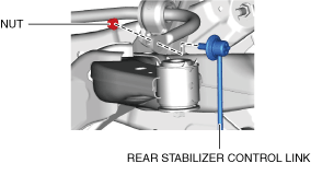
17. Remove the rear stabilizer control link.
am6xuw00011482
|
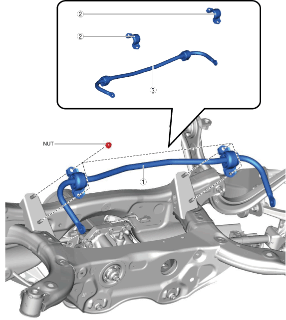
18. Remove in the order indicated in the table.
am6xuw00012824
|
|
1
|
Rear stabilizer component
|
|
2
|
Rear stabilizer bracket
|
|
3
|
Rear stabilizer
|
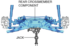
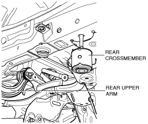
Rear Stabilizer Component Removal Note
1. Support the rear crossmember component with a jack and remove the rear crossmember installation nuts.
am6xuw00011484
|
2. Press down on the rear crossmember component until the rear stabilizer component can be removed from the vehicle using a jack.
ac5wzw00002323
|
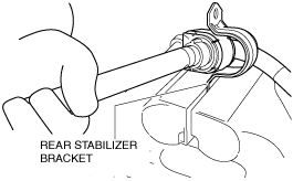
Rear Stabilizer Bracket Removal Note
1. Secure the rear stabilizer bracket flange using a vise.
ac5uuw00000922
|