|
am6xuw00011490
REAR STABILIZER INSTALLATION [4WD]
id0214008042a2
1. After installing the rear stabilizer bracket, verify that the positions of the rear stabilizer bracket and the rear stabilizer bushing are within the range shown in the figure.
am6xuw00011490
|
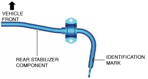
2. Assemble the rear stabilizer component so that the identification mark is on the right side of the vehicle.
ac9uuw00010205
|
3. Temporarily tighten nuts A and B shown in the figure.
ac9uuw00008007
|
4. Tighten nut A.
5. Tighten nut B.
6. Tighten nut A.
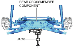
7. Lift up the rear crossmember component using a jack and install the rear crossmember installation nuts.
am6xuw00011492
|
8. Install the rear coil spring. (See REAR COIL SPRING REMOVAL/INSTALLATION.)
9. Install the propeller shaft. (See PROPELLER SHAFT REMOVAL/INSTALLATION.)
10. For SKYACTIV-D 2.2 (Without SCR system) vehicles, perform the following procedure.
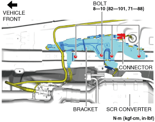
11. For SKYACTIV-D 2.2 (With SCR system) vehicles, perform the following procedure.
am6zzw00017162
|
am6xuw00011494
|
12. Install the following parts: (See EXHAUST SYSTEM REMOVAL/INSTALLATION [SKYACTIV-D 2.2].)
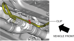
13. Install the insulator.
am6xuw00011495
|
14. Install the fasteners and bolt in the order shown in the figure.
15. Install the following parts: (See FLOOR UNDER COVER REMOVAL/INSTALLATION.)
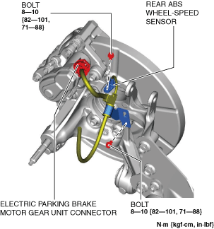
16. Assemble the rear ABS wheel-speed sensor and the electric parking brake motor gear unit connector.
am6xuw00011496
|
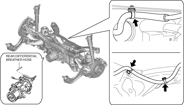
17. Assemble the rear differential breather hose. (See REAR DIFFERENTIAL REMOVAL/INSTALLATION.)
am6xuw00011497
|
18. Install the wheels and tires. (See WHEEL AND TIRE REMOVAL/INSTALLATION.)
19. Connect the negative battery terminal. (See NEGATIVE BATTERY TERMINAL DISCONNECTION/CONNECTION.)
20. Inspect the wheel alignment and adjust it if necessary. (See REAR WHEEL ALIGNMENT.)
Rear Stabilizer Bracket Installation Note
1. If the rear stabilizer bracket cannot be installed by hand, install it using a vise.
am6xuw00011498
|
Suspension Links Installation Note
1. When installing the joint sections with rubber bushings, perform the following procedures.