STEERING GEAR AND LINKAGE INSPECTION
id061300802000
-
Caution
-
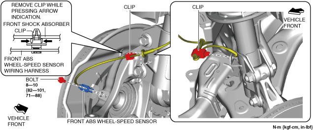
• Performing the following procedures could cause an open circuit in the front ABS wheel-speed sensor wiring harness if it is pulled by mistake. Before servicing, disconnect the front ABS wheel-speed sensor and set it aside so that the wiring harness will not be pulled by mistake.
• Secure the steering wheel using tape or a cable to prevent the steering shaft from rotating after disconnecting the steering shaft. If the steering wheel rotates after the steering shaft and the steering gear and linkage are disconnected, the internal parts of the clock spring could be damaged.
• Do not allow the dust boot of the front stabilizer control link to touch the body, the front shock absorber and coil spring, and the hand tool. Otherwise, the dust boot of the front stabilizer control link could be damaged.
1. Remove the wheels and tires. (See WHEEL AND TIRE REMOVAL/INSTALLATION.)
2. Disconnect the front ABS wheel-speed sensor wiring harness installed to the steering knuckle and set it aside.
3. Remove the following parts:
- (1) Front under cover No.2 (See FRONT UNDER COVER No.2 REMOVAL/INSTALLATION.)
-
- (2) Front under cover No.1 (See FRONT UNDER COVER No.1 REMOVAL/INSTALLATION.)
-
- (3) Front splash shield (See SPLASH SHIELD REMOVAL/INSTALLATION.)
-
4. Detach the tie-rod end from the steering knuckle. (See TIE-ROD END REPLACEMENT.)
5. Disconnect the front lower arm ball joint from the steering knuckle. (See FRONT LOWER ARM REMOVAL/INSTALLATION.)
6. Remove the joint cover. (See STEERING WHEEL AND COLUMN REMOVAL/INSTALLATION.)
7. Disconnect the intermediate shaft from the steering gear and linkage. (See STEERING WHEEL AND COLUMN REMOVAL/INSTALLATION.)
8. Remove the front crossmember component. (See FRONT CROSSMEMBER REMOVAL/INSTALLATION.)
9. Remove the steering gear and linkage from the front crossmember component. (See STEERING GEAR AND LINKAGE REMOVAL/INSTALLATION.)
10. Remove the following parts: (See STEERING GEAR AND LINKAGE DISASSEMBLY.)
-
• Tie-rod end
• Locknut
• Boot clamp
• Boot band
• Boot
• Tie rod
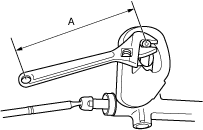
11. Measure the rotation torque of the pinion shaft using a crescent wrench and pull scale. (speed measurement reference 5 rpm)
- (1) Install the crescent wrench to the steering gear.
-
- (2) Measure the length from the pinion shaft center to the crescent wrench end (application point of pull scale) as shown in the figure. This is dimension A.
-
- (3) The rotation torque of the pinion shaft can be calculated using the following formula.
- Pinion shaft rotation torque (N·m {kgf·cm, in·lbf}) = Pull scale reading (N {kgf, lbf}) × A (m {cm, in})
-
Pinion shaft rotation torque (center of rack ± 180°)
-
1.0—1.6 N·m {11—16 kgf·cm, 8.9—14 in·lbf}
-