 |
am6xuw00012209
AIR BAG SYSTEM WARNING LIGHT ILLUMINATES CONSTANTLY [AIR BAG SYSTEM]
id0803a3814400
|
Description
|
• After switching the ignition ON (engine off or on), the air bag system warning light turns on and remains on after approx. 6 s have elapsed.
|
|
Possible cause
|
• DTCs are stored in the PCM.
• Battery malfunction
• Generator system malfunction
• SAS control module connector or terminal malfunction
• SAS control module power supply circuit malfunction
• SAS control module malfunction
• Instrument cluster malfunction
• Malfunction in CAN line between the SAS control module and instrument cluster
• SAS control module body ground circuit malfunction
|
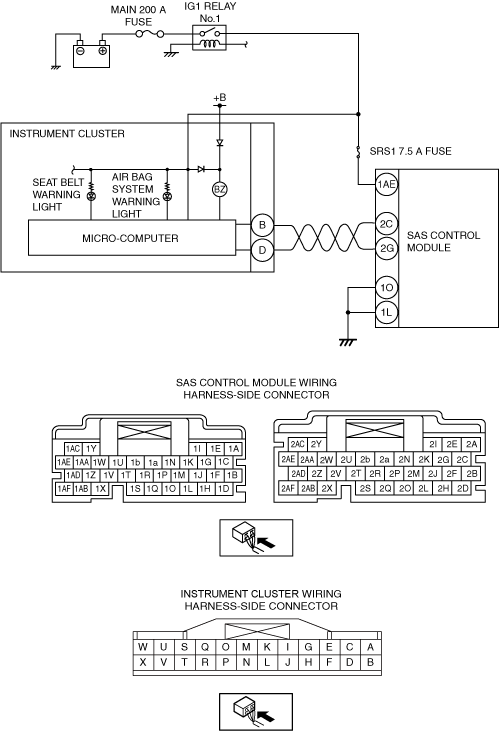
System Wiring Diagram
am6xuw00012209
|
Diagnostic Procedure
|
Step |
Inspection |
Action |
|
|---|---|---|---|
|
1
|
INSPECT IG1 RELAY No.1
• Switch the ignition off.
• Disconnect the negative battery terminal.
• Remove the IG1 relay No.1.
(See RELAY LOCATION.)
• Inspect the IG1 relay No.1.
(See RELAY INSPECTION.)
• Is the IG1 relay No.1 normal?
|
Yes
|
Go to the next step.
|
|
No
|
Replace the IG1 relay No.1, then go to Step 13.
|
||
|
2
|
INSPECT PCM DTC
• Perform the PCM DTC inspection using the M-MDS.
• Are any DTCs present?
|
Yes
|
Go to the applicable DTC inspection.
|
|
No
|
Go to the next step.
|
||
|
3
|
INSPECT BATTERY
• Inspect the battery.
(See BATTERY INSPECTION.)
• Is the battery normal?
|
Yes
|
Go to the next step.
|
|
No
|
Replace or charge the battery.
(See BATTERY RECHARGING.)
Then go to Step 13.
|
||
|
4
|
INSPECT GENERATOR
• Inspect the generator.
• Is the generator normal?
|
Yes
|
Go to the next step.
|
|
No
|
Replace the generator, then go to Step 13.
|
||
|
5
|
VERIFY THAT SAS CONTROL MODULE CONNECTOR IS CONNECTED
• Switch the ignition off.
• Disconnect the negative battery terminal and wait for 1 min or more.
• Verify the condition of the SAS control module connectors.
• Are all SAS control module connectors securely connected?
|
Yes
|
Go to the next step.
|
|
No
|
Reconnect the connector properly, then go to Step 13.
|
||
|
6
|
VERIFY THAT INSTRUMENT CLUSTER CONNECTOR IS CONNECTED
• Remove the instrument cluster.
• Are all instrument cluster connectors securely connected?
|
Yes
|
Go to the next step.
|
|
No
|
Reconnect the connector properly, then go to Step 13.
|
||
|
7
|
INSPECT DTCs IN SAS CONTROL MODULE
• Connect the negative battery terminal.
• Switch the ignition ON (engine off or on).
• Clear the DTC for the SAS control module using the M-MDS.
• Inspect the DTC for the SAS control module on-board diagnostic system.
• Have DTCs been recorded in memory?
|
Yes
|
Perform the applicable DTC inspection, then go to Step 13.
|
|
No
|
Go to the next step.
|
||
|
8
|
INSPECT DTCs IN INSTRUMENT CLUSTER
• Inspect the DTC for the instrument cluster on-board diagnostic system.
• Are the any DTCs present?
|
Yes
|
Perform the applicable DTC inspection, then go to Step 13.
|
|
No
|
Go to the next step.
|
||
|
9
|
VERIFY WHERE MALFUNCTION IS IN WARNING LIGHTS INDICATION CIRCUIT OR ELSEWHERE
• Turn on all warning lights and indicator lights using the instrument cluster PID WL+IL of simulation function using the M-MDS.
• Do other warning and indicator lights illuminate?
|
Yes
|
Go to the next step.
|
|
No
|
Repair the instrument cluster.
Then go to Step 13.
|
||
|
10
|
VERIFY SAS CONTROL MODULE CONNECTOR CONDITION
• Switch the ignition off.
• Disconnect the negative battery terminal and wait for 1 min or more.
• Remove the column cover.
• Disconnect the clock spring connector.
• Remove the glove compartment.
• Disconnect the passenger-side air bag module connector.
• Disconnect the driver and passenger-side seat connectors.
• Remove the B-pillar lower trim.
• Disconnect the driver and passenger-side pre-tensioner seat belt connectors.
• Disconnect the active bonnet actuator connector.
• Disconnect all SAS control module connectors.
• Inspect the connector engagement and connection condition and inspect the terminals for damage, deformation, corrosion, or disconnection.
• Is the connector normal?
|
Yes
|
Go to the next step.
|
|
No
|
Replace the air bag harness, then go to Step 13.
|
||
|
11
|
INSPECT POWER SUPPLY CIRCUIT OF SAS CONTROL MODULE
• Verify that the SAS control module connectors are disconnected.
• Connect the negative battery terminal.
• Switch the ignition ON (engine off or on).
• Measure the voltage at SAS control module at wiring harness-side connector terminal 1AE.
• Is the voltage 8 .1V—15.9V?
|
Yes
|
Go to the next step.
|
|
No
|
Inspect the SRS1 7.5 A fuse and MAIN 200 A fuse.
• If a fuse is blown:
• If a fuse is damaged:
• If the fuse is normal:
Go to Step 13.
|
||
|
12
|
INSPECT SAS CONTROL MODULE BODY GROUND CIRCUIT FOR OPEN CIRCUIT
• SAS control module connectors are disconnected.
• Switch the ignition off.
• Disconnect the negative battery terminal and wait for 1 min or more.
• Inspect for continuity between the following terminals (wiring harness-side) and body ground:
• Is there continuity?
|
Yes
|
Go to the next step.
|
|
No
|
Refer to the wiring diagram and verify whether or not there is a common connector between SAS control module terminal and body ground.
If there is a common connector:
• Determine the malfunctioning part by inspecting the common connector and the terminal for corrosion, damage, or pin disconnection, and the common wiring harness for an open circuit.
• Replace the malfunctioning part.
If there is no common connector:
• Replace the wiring harness which has an open circuit.
Go to the next step.
|
||
|
13
|
VERIFY THAT MALFUNCTION SYMPTOMS DO NOT RECUR AFTER REPAIR
• Connect the SAS control module connectors.
• Reconnect all disconnected connectors.
• Connect the negative battery terminal.
• Switch the ignition ON (engine off or on).
• Does the air bag system warning light illuminate for approx. 6 s and turn off?
|
Yes
|
Verify that there are no DTCs in the memory. If there are no DTCs, the troubleshooting is completed.
|
|
No
|
Recheck malfunction symptoms, then repeat from Step 1.
• If the malfunction recurs, replace the SAS control module.
|
||