FRONT FENDER STAY REMOVAL/INSTALLATION
id091000803900
RH
1. Disconnect the negative battery terminal. (See NEGATIVE BATTERY TERMINAL DISCONNECTION/CONNECTION.)
2. Remove the following parts:
- (1) Set plate (See SET PLATE REMOVAL/INSTALLATION.)
-
- (2) Front bumper (See FRONT BUMPER REMOVAL/INSTALLATION.)
-
- (3) Theft-deterrent siren (with theft-deterrent system) (See THEFT-DETERRENT SIREN REMOVAL/INSTALLATION.)
-
- (4) Washer tank (See WASHER TANK REMOVAL/INSTALLATION.)
-
- (5) Front bumper slider (RH) (See BUMPER SLIDER REMOVAL/INSTALLATION.)
-
- (6) Front combination light (RH) (See FRONT COMBINATION LIGHT REMOVAL/INSTALLATION.)
-
- (7) Side step molding (RH) (See SIDE STEP MOLDING REMOVAL/INSTALLATION.)
-
- (8) Front fender panel (RH) (See FRONT FENDER PANEL REMOVAL/INSTALLATION.)
-
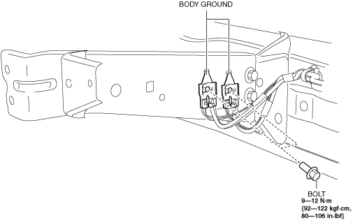
3. Remove the bolts and then remove the body grounds.
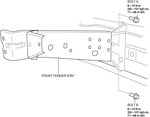
4. Remove bolt A and bolt B.
5. Remove the front fender stay.
6. Install in the reverse order of removal. (See Front Fender Stay Newly Replace Note.)
7. Adjust the headlight aiming. (See HEADLIGHT AIMING.)
LH
1. Disconnect the negative battery terminal. (See NEGATIVE BATTERY TERMINAL DISCONNECTION/CONNECTION.)
2. Remove the following parts:
- (1) Set plate (See SET PLATE REMOVAL/INSTALLATION.)
-
- (2) Front bumper (See FRONT BUMPER REMOVAL/INSTALLATION.)
-
- (3) Capacitor (with i-ELOOP) (See CAPACITOR (i-ELOOP) REMOVAL/INSTALLATION [i-ELOOP].)
-
- (4) Theft-deterrent siren (with theft-deterrent system) (See THEFT-DETERRENT SIREN REMOVAL/INSTALLATION.)
-
- (5) Front bumper slider (LH) (See BUMPER SLIDER REMOVAL/INSTALLATION.)
-
- (6) Front combination light (LH) (See FRONT COMBINATION LIGHT REMOVAL/INSTALLATION.)
-
- (7) Side step molding (LH) (See SIDE STEP MOLDING REMOVAL/INSTALLATION.)
-
- (8) Front fender panel (LH) (See FRONT FENDER PANEL REMOVAL/INSTALLATION.)
-
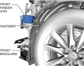
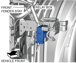
3. Remove the fastener.
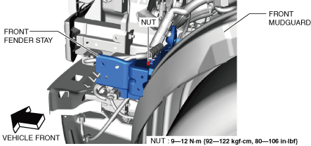
4. Remove the nut.
5. Remove the relay box.
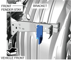
6. Remove the bracket.
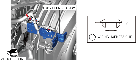
7. Remove the wiring harness clips.
8. Remove bolt A and bolt B.
9. Remove the front fender stay.
10. Install in the reverse order of removal. (See Front Fender Stay Newly Replace Note.)
11. Adjust the headlight aiming. (See HEADLIGHT AIMING.)
Front Fender Stay Newly Replace Note
-
Caution
-
• If the bolt connection area is painted when the front fender stay is replaced, it could cause a malfunction in the PCM. Before painting the replaced front fender stay, refer to the [Paint Procedure For Replaced Front Fender Stay] in the bodyshop manual.