1. Remove the battery. (See BATTERY REMOVAL/INSTALLATION [LF, L3].)
2. Remove the battery tray. (See BATTERY REMOVAL/INSTALLATION [LF, L3].)
3. Remove the radiator. (See RADIATOR REMOVAL/INSTALLATION [LF, L3].)
4. Drain the transaxle oil.
5. Remove the plug hole plate. (L3 engine model)
(See PLUG HOLE PLATE REMOVAL/INSTALLATION [L3].)
6. Remove the P/S oil pump with the oil hose still connected and position the P/S oil pump so that it is out of the way. (See POWER STEERING OIL PUMP REMOVAL/INSTALLATION.)
7. Remove the A/C compressor with the pipes still connected. Position the A/C compressor so that it is out of the way. Use wire or rope to secure.
8. Remove the joint shaft. (See JOINT SHAFT REMOVAL/INSTALLATION.)
9. Remove the front drive shaft (LH) from the transaxle. (See DRIVE SHAFT REMOVAL/INSTALLATION.)
10. Remove the air cleaner, intake air duct, accelerator cable and bracket, and vacuum hose. (See INTAKE-AIR SYSTEM REMOVAL/INSTALLATION [LF, L3].)
11. Remove the ATF filter and selector cable. (ATX) (See AUTOMATIC TRANSAXLE REMOVAL/INSTALLATION [FN4A-EL].)
12. Remove the vacuum hose and heater hose.
13. Remove the release cylinder and control cable. (MTX) (See MANUAL TRANSAXLE REMOVAL/INSTALLATION [G35M-R].)
14. Remove the plastic fuel hose. (See Plastic Fuel Hose Removal Note.) (See Plastic Fuel Hose Installation Note.)
15. Disconnect the wiring harness from the engine side.
16. Remove the front pipe. (See EXHAUST SYSTEM REMOVAL/INSTALLATION [LF, L3].)
17. Remove in the order indicated in the table.
18. Install in the reverse order of removal.
19. Start the engine and:
20. Perform a road test.
|
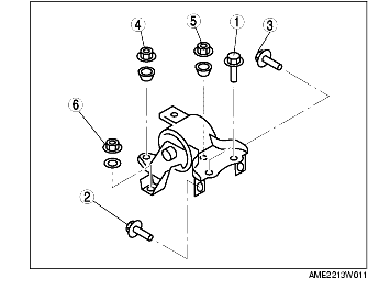
1
|
No.1 Engine mount rubber
|
|
2
|
No.1 Engine mount bracket
|
|
3
|
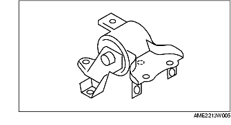
No.4 Engine mount bracket and No.4 Engine mount rubber
|
|
4
|
Engine ground
|
|
5
|
No.3 Engine joint bracket
|
|
6
|
Engine, transaxle
|
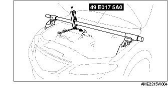
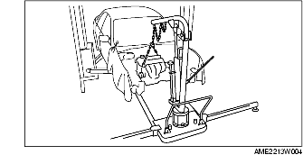
1. Suspend the engine using the SST.
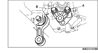
2. Remove through bolt A on the No.1 engine mount bracket side.
3. Loosen through bolt B on the front crossmember side until approximately three pitches are showing.
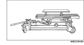
1. Secure the engine and the transaxle using an engine jack and attachment as shown.
2. Remove the SST.
3. Secure the engine and the transaxle using a hoist.
4. Remove the No.4 engine mount bracket and engine mount rubber together as a unit.
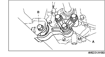
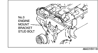
1. Tighten the No.3 engine mount bracket stud bolt.
2. Tighten the No.3 engine joint bracket bolt and nut in the order as shown.
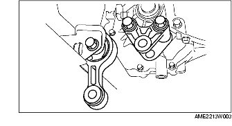
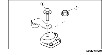
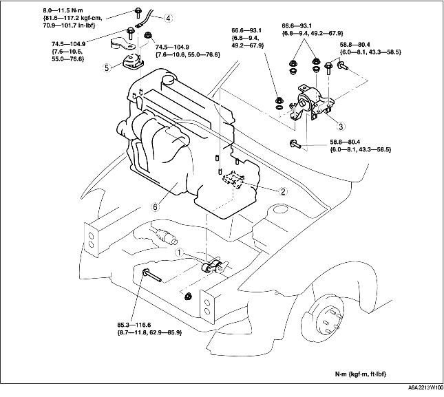
1. Tighten the No.4 engine mount bracket and No.4 engine mount rubber bolt and nut in the order as shown.
|
Bolt or nut No.
|
Tightening torque
(N·m {kgf·m, ft·lbf})
|
|---|---|
|
1, 2, 3
|
58.8-80.4 {6.0-8.1, 43.3-58.5} |
|
4, 5, 6
|
66.6-93.1 {6.8-9.4, 49.2-67.9} |
2. Secure the engine and the transaxle using an engine jack and attachment as shown.
3. Remove the hoist and secure the engine and transaxle using SST.
1. Tighten No.1 engine mount bracket bolt A.
2. Tighten No.1 engine mount bracket bolt B.
1. Tighten through bolt A on the No.1 engine mount bracket.
2. Tighten through bolt B on the front crossmember side.