 |
am6zzw00003114
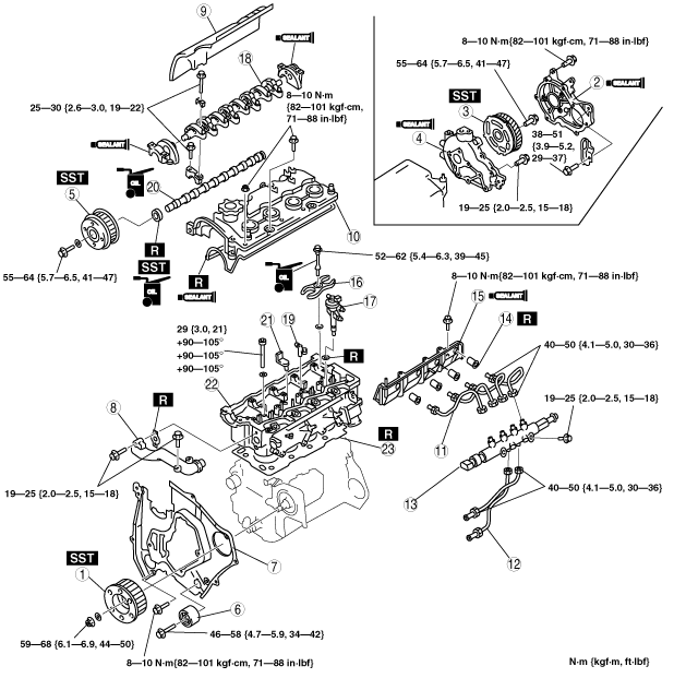
CYLINDER HEAD GASKET REPLACEMENT [MZR-CD (RF Turbo)]
id0110f1800700
1. Remove the timing belt. (See TIMING BELT REMOVAL/INSTALLATION [MZR-CD (RF Turbo)].)
2. Remove the battery and tray. (See BATTERY REMOVAL/INSTALLATION [MZR-CD (RF Turbo)].)
3. Drain the engine coolant. (See ENGINE COOLANT REPLACEMENT [MZR-CD (RF Turbo)].)
4. Remove the vacuum pump. (See VACUUM PUMP REMOVAL/INSTALLATION [MZR-CD (RF Turbo)].)
5. Remove the turbocharger. (See EXHAUST SYSTEM REMOVAL/INSTALLATION [MZR-CD (RF Turbo)].)
6. Remove all the glow plugs. (See GLOW PLUG REMOVAL/INSTALLATION [MZR-CD (RF Turbo)].)
7. Remove the radiator upper hose. (See RADIATOR REMOVAL/INSTALLATION [MZR-CD (RF Turbo)].)
8. Remove the EGR pipe. (See EGR VALVE REMOVAL/INSTALLATION [MZR-CD (RF Turbo)].)
9. Set the EGR cooler out of the way. (See EGR COOLER REMOVAL/INSTALLATION [MZR-CD (RF Turbo)].)
10. Remove in the order shown in the table.
11. Install in the reverse order of removal.
12. Refill the engine coolant. (See ENGINE COOLANT REPLACEMENT [MZR-CD (RF Turbo)].)
13. Inspect valve clearance. (See VALVE CLEARANCE INSPECTION [MZR-CD (RF Turbo)].)
14. Inspect the engine oil level.
15. Inspect the compression. (See COMPRESSION INSPECTION [MZR-CD (RF Turbo)].)
16. Start the engine and:
am6zzw00003114
|
|
1
|
Supply pump pulley
|
|
2
|
Gear cover
(See Gear Cover Installation Note.)
|
|
3
|
Drive gear
(See Drive Gear Removal Note.)
(See Drive Gear Installation Note.)
|
|
4
|
Gear case
(See Gear Case Installation Note.)
|
|
5
|
Camshaft pulley
(See Camshaft Pulley Removal Note.)
|
|
6
|
Idler
(See Idler Installation Note.)
|
|
7
|
Seal plate
(See Seal Plate Removal Note.)
(See Seal Plate Installation Note.)
|
|
8
|
Water outlet
|
|
9
|
Insulator
|
|
10
|
Cylinder head cover
|
|
11
|
Fuel Injection pipe (Fuel injector side)
|
|
12
|
Fuel Injection pipe (Fuel supply pump side)
|
|
13
|
Common rail
|
|
14
|
Nozzle seal
|
|
15
|
Side wall
(See Side Wall Installation Note.)
|
|
16
|
Fuel injector bracket
|
|
17
|
Fuel injector
|
|
18
|
Rocker arm and rocker arm shaft
|
|
19
|
Rocker bridge
|
|
20
|
Camshaft
|
|
21
|
Breather pipe
|
|
22
|
Cylinder head
(See Cylinder Head Removal Note.)
|
|
23
|
Cylinder head gasket
|
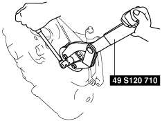
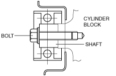
Supply Pump Pulley Removal Note
1. Hold the supply pump pulley using the SST and remove the supply pump pulley lock nut.
am6zzw00003642
|
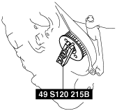
2. Separate the supply pump pulley from the supply pump shaft using the SST.
am6zzw00003643
|
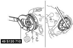
Drive Gear Removal Note
1. Hold the camshaft using the SST.
2. Remove the drive gear lock bolt.
am6zzw00003644
|
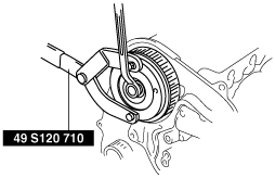
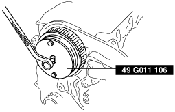
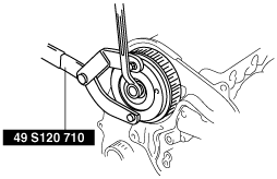
Camshaft Pulley Removal Note
1. Hold the camshaft using the SST.
2. Remove the camshaft pulley lock bolt.
am6zzw00003645
|
3. Remove the camshaft pulley using the SST.
am6zzw00003646
|
Seal Plate Removal Note
1. Remove the seal plate from the engine component. However, the seal plate cannot be removed completely. Separate the seal plate from the engine component by removing the fitting bolts so that the cylinder head can be removed.
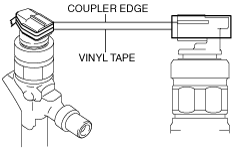
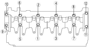
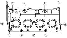
Cylinder Head Cover Removal Note
1. Wrap the fuel injector coupler with vinyl tape 2 times covering the coupler edge so as not to damage the injector seal.
am6zzw00003647
|
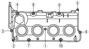
2. Loosen the bolts in the order shown in the figure.
am6zzw00003106
|
3. Remove the cylinder head cover carefully so as not to damage the injector seal from coupler edge.
4. Verify that there are no cracks or rips on the injector seal.
5. If there are any cracks or rips, remove the injector seal using the following procedure to replace it with a new one.
am3zzw00003986
|
Rocker Arm and Rocker Arm Shaft Removal Note
1. Loosen the bolts in two or three steps in the order shown.
am6zzw00003654
|
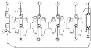
Cylinder Head Removal Note
1. Loosen the cylinder head bolts in two or three steps in the order shown.
am3zzw00003988
|
Cylinder Head Installation Note
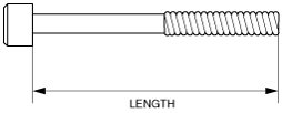
1. Measure the length of each cylinder head bolt.
am3zzw00003989
|
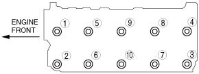
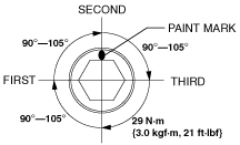
2. Tighten the bolts in two or three steps in the order shown.
am3zzw00004175
|
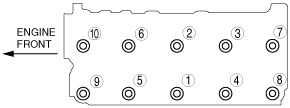
3. Put a paint mark on each bolt head.
4. Using the marks as a reference, tighten the bolts by turning each 90°—105° in the sequence shown.
5. Further tighten each bolt by turning another 90°—105°.
6. Then further tighten each bolt by turning another 90°—105°.
am6zzw00003115
|
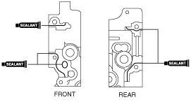
Rocker Arm and Rocker Arm Shaft Installation Note
1. Apply sealant as shown in the figure.
am6zzw00003117
|
2. Install the camshaft caps according to the cap number.
3. Install the rocker arm shaft plane side upward.
am3zzw00003992
|
4. Tighten the bolts in two or three steps in the order shown.
am6zzw00003655
|
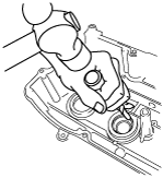
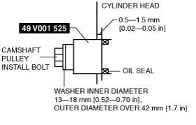
5. Apply clean engine oil to the new oil seal.
6. Push the oil seal slightly in by hand.
7. Tap the oil seal into the cylinder head using the SST and camshaft pulley install bolt and suitable washer (Inner diameter 13—18 mm {0.52—0.70 in}, Outer diameter over 42 mm {1.7 in}).
am6zzw00003116
|
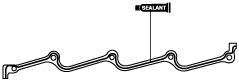
Side Wall Installation Note
1. Apply silicone sealant as shown in the figure.
am6zzw00003656
|
Fuel Injection Pipe Installation Note
Cylinder Head Cover Installation Note
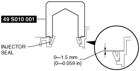
1. If the injector seal has been removed, press it in using the SST and a hammer.
am6zzw00003657
|
2. Wrap the fuel injector coupler with vinyl tape 2 times covering the coupler edge so as not to damage the injector seal.
am6zzw00003647
|
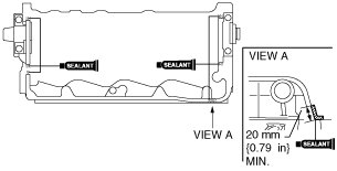
3. Apply silicone sealant to the shaded areas.
am6zzw00003658
|
4. Install the cylinder head cover so as not to damage the injector seal from the coupler edge.
5. Verify that the injector seal is not damaged, then remove the vinyl tape wrapped around the fuel injector coupler.
6. Tighten the bolts in the order shown.
am6zzw00003107
|
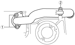
Water Outlet Installation Note
1. Tighten the bolts in the order shown.
am6zzw00003648
|
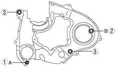
Seal Plate Installation Note
1. Install the seal plate and hand tighten the bolt in the order A to B.
2. Tighten the bolts in the order shown.
am6zzw00003649
|
Idler Installation Note
am6zzw00003650
|
Camshaft Pulley Installation Note
1. Hold the camshaft using the SST.
am6zzw00003651
|
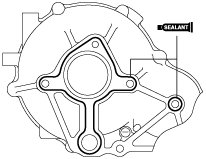
Gear Case Installation Note
1. Apply silicone sealant as shown in the figure.
am6zzw00003652
|
2. Tighten the bolts in clockwise order.
Drive Gear Installation Note
1. Hold the camshaft using the SST.
2. Tighten the drive gear lock bolt.
am6zzw00003644
|
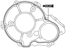
Gear Cover Installation Note
1. Apply silicone sealant as shown in the figure.
am6zzw00003653
|
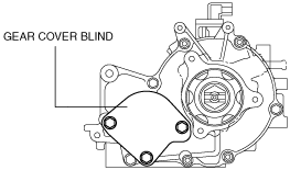
2. Tighten the gear cover blind bolts in as shown in the figure.
am6zzw00003691
|
Supply Pump Pulley Installation Note
1. Hold the supply pump pulley using the SST and install the the supply pump pulley lock nut.
am6zzw00003642
|