DTC P0841:00 [FS5A-EL]
id050221822500
DTC P0841:00 |
Oil pressure switch circuit malfunction |
---|---|
DETECTION CONDITION
|
• When DTC P0731:00, P0732:00, P0733:00 and P0734:00 are not output and 10 s or more has passed.
Diagnostic support note:
• This is a continuous monitor (CCM).
• The MIL does not illuminate.
• A PENDING CODE is not available.
• FREEZE FRAME DATA is not available.
• The AT warning light does not illuminate.
• The DTC is stored in the TCM memory.
|
POSSIBLE CAUSE
|
• ATF level low
• Deteriorated ATF
• Line pressure low
• Oil pressure switch malfunction
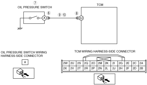
• Open circuit in wiring harness between oil pressure switch terminal A and TCM terminal 2J
• Short to ground in wiring harness between oil pressure switch terminal A and TCM terminal 2J
• Damaged connector between oil pressure switch and TCM
• Control valve stuck
• TCM malfunction
|
![]() |
Diagnostic procedure
STEP |
INSPECTION |
ACTION |
|
---|---|---|---|
1
|
VERIFY RELATED SERVICE INFORMATION AVAILABILITY
• Verify related Service Information availability.
• Is any related repair Information available?
|
Yes
|
Perform repair or diagnosis according to the available repair information.
• If the vehicle is not repaired, go to the next step.
|
No
|
Go to the next step.
|
||
2
|
INSPECT ATF CONDITION
• Inspect the ATF condition.
• Is it normal?
|
Yes
|
Go to the next step.
|
No
|
Replace the ATF, then go to Step 10.
|
||
3
|
INSPECT ATF LEVEL
• Start the engine.
• Warm up the ATX.
• Is the ATF level within the specification?
|
Yes
|
Go to the next step.
|
No
|
Add ATF to the specified level, then go to Step 10.
|
||
4
|
INSPECT LINE PRESSURE
• Start the engine.
• Measure the line pressures.
• Are the line pressures within the specifications?
|
Yes
|
Go to the next step.
|
No
|
All ranges: Replace the oil pump, then go to Step 10.
Any ranges: Replace the primary control valve body, then go to Step 10.
|
||
5
|
INSPECT OIL PRESSURE SWITCH CONNECTOR FOR POOR CONNECTION
• Disconnect the shift oil pressure switch connector.
• Inspect for poor connection (such as damaged/pulled-out pins, corrosion).
• Is the connection normal?
|
Yes
|
Go to the next step.
|
No
|
Repair or replace the connector and/or terminals, then go to Step10.
|
||
6
|
INSPECT CONTINUITY
• Inspect for continuity between oil pressure switch terminal A (part-side) and body ground.
• Is there continuity?
|
Yes
|
Replace the oil pressure switch, then go to Step 10.
|
No
|
Go to the next step.
|
||
7
|
INSPECT TCM CONNECTOR FOR POOR CONNECTION
• Disconnect the TCM connector.
• Inspect for poor connection (such as damaged/pulled-out pins, corrosion).
• Is the connection normal?
|
Yes
|
Go to the next step.
|
No
|
Repair or replace the connector and/or terminals, then go to Step 10.
|
||
8
|
INSPECT OIL PRESSURE SWITCH CIRCUIT FOR OPEN CIRCUIT
• Inspect for continuity between TCM terminal 2J (wiring harness-side) and oil pressure switch terminal A (wiring harness-side).
• Is there continuity between terminals?
|
Yes
|
Go to the next step.
|
No
|
Repair or replace the wiring harness, then go to Step 10.
|
||
9
|
INSPECT TCM CIRCUIT FOR SHORT TO GROUND
• Switch the ignition to off.
• Inspect for continuity between TCM terminal 2J (wiring harness-side) and body ground.
• Is there continuity?
|
Yes
|
Repair or replace the wiring harness, then go to the next step.
|
No
|
Replace the oil pressure switch, then go to the next step.
|
||
10
|
VERIFY TROUBLESHOOTING OF DTC P0841:00 COMPLETED
• Make sure to reconnect all the disconnected connectors.
• Clear the DTC from the memory using the M-MDS.
• Drive the vehicle and make sure that gears shift smoothly from 1GR to 5GR.
• Is the same DTC present?
|
Yes
|
Replace the TCM, then go to the next step.
|
No
|
No concern is detected. Go to the next step.
|
||
11
|
VERIFY AFTER REPAIR PROCEDURE
• Perform the “After Repair Procedure”.
• Are any DTCs present?
|
Yes
|
Go to the applicable DTC inspection.
|
No
|
DTC troubleshooting completed.
|