 |
ar8uuw00001791
ELECTRIC POWER STEERING (EPS) ON-BOARD DIAGNOSIS
id060200801800
On-Board Diagnostic (OBD) Test Description
Read/clear diagnostic results
PID/Data monitor and record
Active command modes
Reading DTCs Procedure
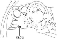
1. Connect the M-MDS to the DLC-2.
ar8uuw00001791
|
2. After the vehicle is identified, select the following items from the initialization screen of the M-MDS.
3. Verify the DTC according to the directions on the screen.
4. After completion of repairs, clear all DTCs stored in the EPS. (See Clearing DTCs Procedures.)
Clearing DTCs Procedures
1. Connect the M-MDS to the DLC-2.
ar8uuw00001791
|
2. After the vehicle is identified, select the following items from the initialization screen of the M-MDS.
3. Verify the DTC according to the directions on the screen.
4. Press the clear button on the DTC screen to clear the DTC.
5. Turn the ignition switch to the LOCK position.
6. Turn the ignition switch to the ON position and wait for 5 s or more.
7. Perform DTC inspection. (See Reading DTCs Procedure.)
8. Verify that no DTCs are displayed.
PID/Data Monitor and Record Procedure
1. Connect the M-MDS to the DLC-2.
ar8uuw00001791
|
2. After the vehicle is identified, select the following items from the initialization screen of the M-MDS.
3. Select the applicable PID from the PID table.
4. Verify the PID data according to the directions on the screen.
Active Command Modes Procedure
1. Connect the M-MDS to the DLC-2.
ar8uuw00001791
|
2. After the vehicle is identified, select the following items from the initialization screen of the M-MDS.
3. Select the active command modes from the PID table.
4. Perform the active command modes, inspect the operations for each parts.
DTC Table
|
DTC |
Diagnosis system component |
Page |
|---|---|---|
|
M-MDS |
||
|
B1318
|
Battery power supply
|
(See DTC B1318.)
|
|
B1342
|
EPS control module
|
(See DTC B1342.)
|
|
B2141
|
EPS system (neutral position setting not performed)
|
(See DTC B2141.)
|
|
B2278
|
Torque sensor
|
(See DTC B2278.)
|
|
C1099
|
EPS motor
|
(See DTC C1099.)
|
|
U0073
|
CAN bus communication error
|
|
|
U1900
|
CAN communication error
|
|
|
U2023
|
CAN communication error
|
PID/DATA Monitor Table
|
PID Name (Definition) |
Unit/Condition |
Condition/Specification |
Action |
EPS control module terminal |
|---|---|---|---|---|
|
B+
(System battery voltage value)
|
V
|
• IG switch ON: B+
|
Inspect battery. (See BATTERY INSPECTION [13B-MSP].)
Inspect power supply circuit (such as IG switch, fuse).
|
2P
|
|
CCNT
(Number of continuous codes)
|
—
|
• DTCs are detected: 1—255
• No DTCs are detected: 0
|
Perform inspection using appropriate DTC.
|
—
|
|
EPS_MTR
(EPS motor drive signal)
|
A
|
• Steering wheel is not turned: Near 0 A
• Steering wheel is turned right: 0—127 A
• Steering wheel is turned left: 0— -128 A
|
Inspect EPS control module. (See EPS CONTROL MODULE INSPECTION.)
Inspect EPS motor circuit.
Inspect power supply circuit (such as IG switch, fuse).
|
4A, 4B
|
|
EPSLAMP
(EPS warning light output state)
|
On/Off
|
• EPS warning light is illuminated: On
• EPS warning light is not illuminated: Off
|
Inspect EPS control module. (See EPS CONTROL MODULE INSPECTION.)
Inspect instrument cluster.
|
—
|
|
RPM
(Engine speed signal)
|
RPM
|
• Engine speed 1,000 rpm: 1000 RPM
|
Inspect PCM. (See PCM INSPECTION [13B-MSP].)
|
—
|
|
TRQ_S_CORR
(System neutral position setting)
|
Nm
|
• Steering wheel is not turned: Near 0 Nm
(If system neutral position setting has not been performed, 31.75 Nm is output.)
|
Perform EPS system neutral position setting. (See EPS SYSTEM NEUTRAL POSITION SETTING.)
|
—
|
|
TRQ_SENS
(Torque sensor signal)
|
Nm
|
• Steering wheel is not turned: Near 0 Nm
• Steering wheel is turned right: 0—31.75 Nm
• Steering wheel is turned left: 0— -32 Nm
|
Inspect torque sensor. (See TORQUE SENSOR INSPECTION.)
Inspect torque sensor circuit.
|
3A, 3B, 3C
|
|
VSS
(Vehicle speed signal)
|
KPH, MPH
|
• Vehicle is stopped:
0 KPH/0 MPH
• Vehicle speed 20 km/h {12 mph}: 20 KPH/12 MPH
|
Inspect PCM. (See PCM INSPECTION [13B-MSP].)
Inspect instrument cluster. (See INSTRUMENT CLUSTER INSPECTION.)
Inspect DSC HU/CM. (See DSC HU/CM INSPECTION.)
|
—
|
Active Command Mode Table
|
Command Name |
Definition |
Operation |
Note |
|---|---|---|---|
|
TRQ_S_CAL
|
EPS system neutral position setting
|
On/Off
|
Ignition switch at ON
|