1. Remove the battery tray. (See BATTERY REMOVAL/INSTALLATION [L3, AJ (3.0L Duratec)].)
2. Remove the air cleaner outlet tube and air cleaner. (See AIR CLEANER REMOVAL/INSTALLATION [AJ (3.0L Duratec)].)
3. Lift up the vehicle.
4. Remove the lower radiator air deflectors.
5. Drain the engine coolant. (See ENGINE COOLANT REPLACEMENT [AJ (3.0L Duratec)].)
6. Lower the vehicle.
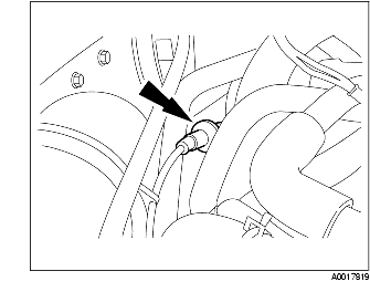
7. Disconnect the fuel line. (See BEFORE SERVICE PRECAUTION [AJ (3.0L Duratec)].)
8. Remove the water pump drive belt. (See DRIVE BELT REPLACEMENT [AJ (3.0L Duratec)].)
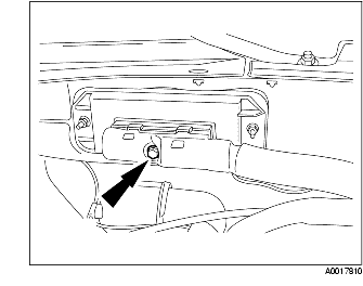
9. Disconnect the accelerator cable.
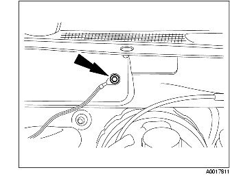
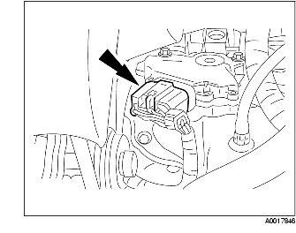
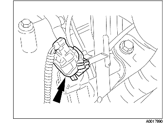
10. Disconnect purge solenoid valve.
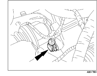
11. Disconnect the PCM connector.
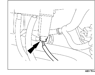
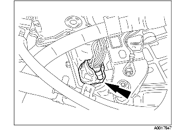
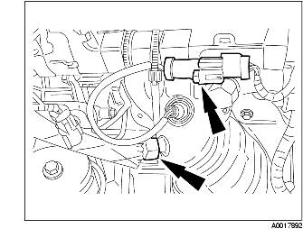
12. Disconnect the ground wire.
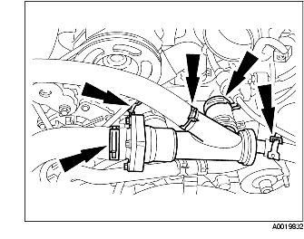
13. Disconnect the hoses and position the thermostat housing and hose assembly out of the way.
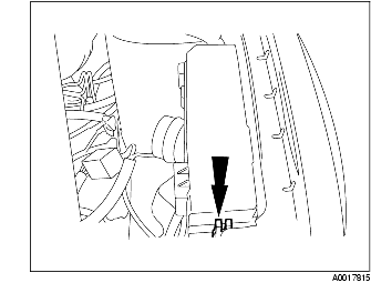
14. Disconnect the connector from BJB.
15. Remove the BJB cover.
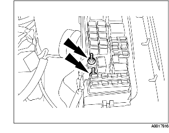
16. Remove the nuts and the cables.
17. Disconnect the transaxle linkage.
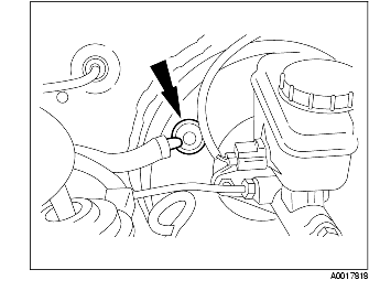
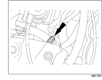
18. Disconnect the brake booster vacuum hose.
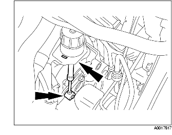
19. Disconnect the vacuum line.
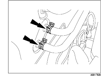
20. Disconnect the heater hoses.
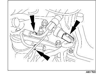
21. Disconnect the power steering return line.
22. Disconnect the power steering line.
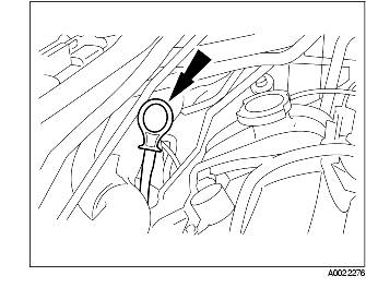
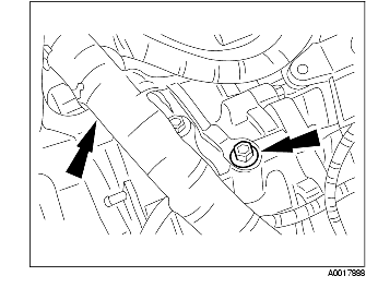
23. Remove the oil level indicator.
24. Remove the front pipe. (See FRONT PIPE REMOVAL/INSTALLATION [AJ (3.0L Duratec)].)
25. Remove the catalytic converter. (See CATALYTIC CONVERTER REMOVAL/INSTALLATION [AJ (3.0L Duratec)].)
26. Remove the A/C compressor. Do not disconnect the A/C compressor pipe while positioning it out of the way.
27. Remove both the front wheels and tires. (See WHEEL AND TIRE REMOVAL/INSTALLATION.)
28. Remove the propeller shaft. (See PROPELLER SHAFT REMOVAL/INSTALLATION.)
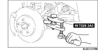
29. Separate the LH and RH ball joints.
30. Separate the LH and RH outer ball joints from the steering knuckle using the SST.
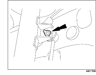
31. Separate the LH and RH stabilizer control link from the shock absorber.
32. Remove the bolt and position the LH and RH ABS wheel speed sensors out of the way.
33. Remove the LH and RH brake calipers from the steering knuckles and support the struts.
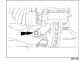
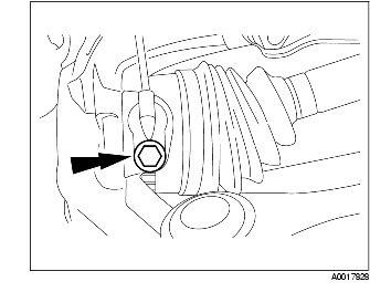
34. Remove the boot mounting nut.
35. Separate the bolt between the intermediate shaft and steering gear.
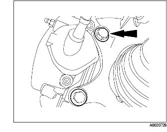
36. Remove the transaxle line bracket bolt.
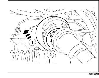
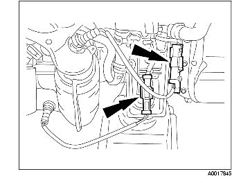
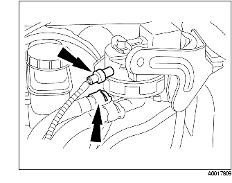
37. Disconnect the two transaxle cooler lines.
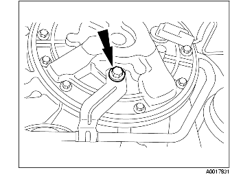
38. Remove the torque converter inspection cover.
39. Remove the torque converter nuts.
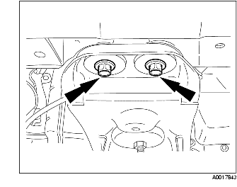
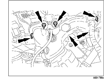
40. Remove the four bolts.
41. Determine the appropriate lift position.
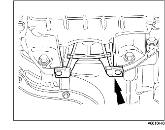
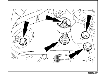
42. Remove the bolts and nuts, and then remove the No.3 engine mount bracket.
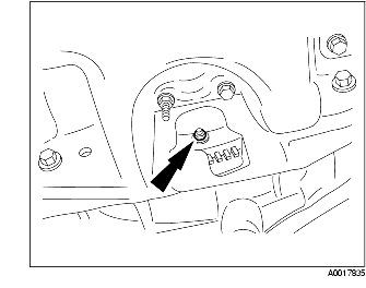
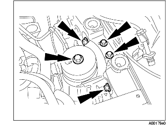
43. Remove the bolts and No.4 engine mount rubber.
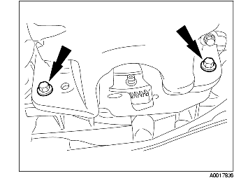
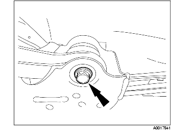
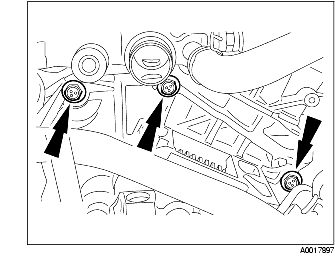
44. Remove two front cross member bolts.
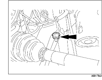
45. Remove two front cross member nuts.
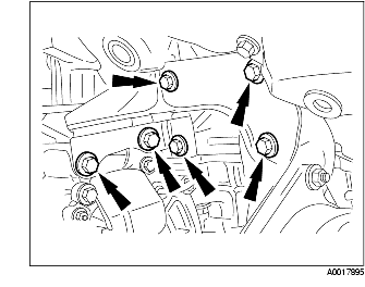
46. Remove the four bolts from the engine mount member.
47. Remove the transaxle from the vehicle.
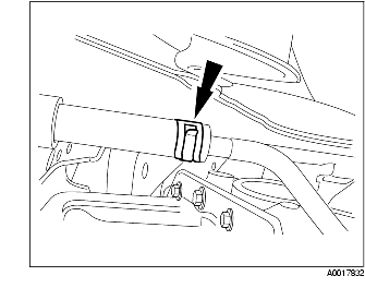
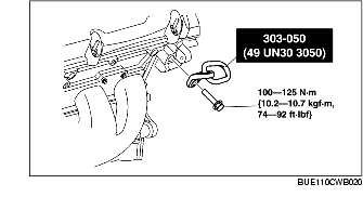
48. Install the SST to the cylinder head (RH) at the position shown in the figure using the bolt of part number 9XG0 16 27X1 or the bolt of M12X1.75 with nominal length 33 mm.
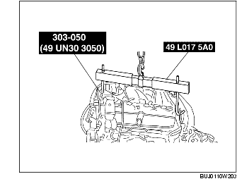
49. Using the SST, remove the transaxle from the lift and set it down on the floor or a suitable table.
50. Disconnect the HO2S.
51. Disconnect the transaxle range switch.
52. Disconnect the transaxle connector.
53. Remove the bolt and separate the transaxle control harness from the bracket.
54. Remove the two bolts, the starter and wiring harness.
55. Disconnect the knock sensor jumper electrical connector.
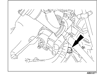
56. Disconnect the output shaft speed sensor electrical connector.
57. Disconnect the HO2S and the EGR tube from the exhaust manifold.
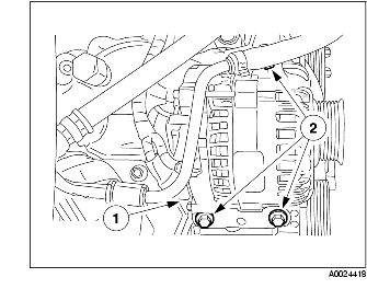
58. Remove the generator.
59. Remove the six RH exhaust manifold nuts and gasket.
60. Remove the bolts and position the joint bracket out of the way.
61. Remove the five transaxle bolts.
62. Remove the engine from the transaxle.