 |
atraaw00003535
CYLINDER HEAD GASKET REPLACEMENT [L3]
id0110a4800700
1. Remove the splash shield (LH).
2. Drain the engine coolant.
3. Remove the timing chain. (See TIMING CHAIN REMOVAL/INSTALLATION [L3].)
4. Disconnect the generator, but do not remove it from the vehicle.
5. Fix the generator using a rope to prevent it from falling. (See GENERATOR REMOVAL/INSTALLATION [L3 L.H.D.].)(See GENERATOR REMOVAL/INSTALLATION [L3 R.H.D.].)
6. Remove the cooling fan assembly.
7. Remove the exhaust manifold. (See EXHAUST SYSTEM REMOVAL/INSTALLATION [L3].)
8. Remove the intake manifold. (See INTAKE-AIR SYSTEM REMOVAL/INSTALLATION [L3].)
9. Remove the ignition coil (R.H.D.model). (See IGNITION COIL REMOVAL/INSTALLATION [L3 R.H.D.].)
10. Disconnect the heater hose, bypass hose, and radiator hose.
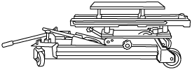
11. To firmly support the engine, first set the engine jack and attachment to the oil pan.
atraaw00003535
|
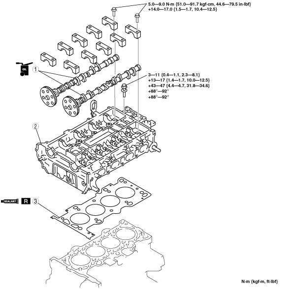
12. Remove in the order indicated in the table.
13. Install in the reverse order of removal.
14. Inspect the compression. (See COMPRESSION INSPECTION [L3].)
atraaw00003546
|
|
1
|
Camshaft
(See Camshaft Removal Note.)
(See Camshaft Installation Note.)
|
|
2
|
Cylinder head
(See Cylinder Head Removal Note.)
|
|
3
|
Cylinder head gasket
|
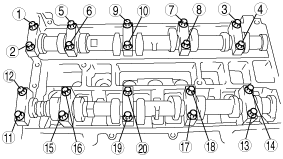
Camshaft Removal Note
1. Loosen the camshaft cap bolts in two or three steps in the order shown.
am5ezw00006860
|
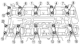
Cylinder Head Removal Note
1. Loosen the cylinder head bolts in two or three steps in the order shown.
am5ezw00006861
|
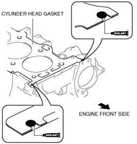
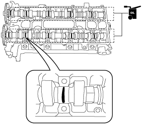
Cylinder Head Gasket Installation Note
1. Apply silicone sealant to the areas shown in the figure.
acxaaw00001646
|
2. Install the cylinder block with a new cylinder head gasket.
3. Apply silicone sealant to the areas shown in the figure.
acxaaw00001647
|
4. Install the cylinder head referring to the Cylinder Head Installation Note.
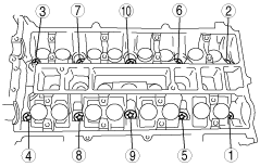
Cylinder Head Installation Note
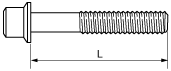
1. Measure the length of each cylinder head bolt.
am5ezw00006862
|
2. Tighten the cylinder head bolts in the order shown using the following 5 steps.
am5ezw00006863
|
Camshaft Installation Note
1. Apply the gear oil (SAE No. 90 or equivalent) to each journal of the cylinder head as shown in the figure.
atraaw00003537
|
2. Set the cam position of No.1 cylinder at the top dead center (TDC) and install the camshaft.
3. Apply the gear oil (SAE No. 90 or equivalent) to each journal of the camshaft as shown in the figure.
atraaw00003538
|
4. Temporarily tighten the camshaft bearing caps evenly in two or three steps.
5. Tighten the camshaft cap bolts in the order shown with the following two steps.
am5ezw00006866
|