1. Engine control system check
Refer to "51.Engine Control 1A.Troubleshooting(RZ4E-TC) Diagnostic system check-engine controls".
2. Prioritized DTC check
1) Connect the scan tool.
2) Turn OFF the ignition switch for 30 seconds or more.
3) Turn ON the ignition switch.
4) Observe the DTC information with a scan tool. Is DTC P0112, P0113, P0117, P0118, P0234, P0237, P0238, P0299, P0638, P2227, P2228, or P2229 set at the same time?
Yes
Go to the applicable DTC diagnosis.
Refer to "51.Engine Control 1A.Troubleshooting(RZ4E-TC) DTC P0234 (Flash Code 42) Turbocharger Overboost Condition".
Refer to "51.Engine Control 1A.Troubleshooting(RZ4E-TC) DTC P0299 (Flash Code 65) Turbocharger Underboost".
Refer to "51.Engine Control 1A.Troubleshooting(RZ4E-TC) DTC P2228 (Flash Code 71) Barometric Pressure Circuit Low".
Refer to "51.Engine Control 1A.Troubleshooting(RZ4E-TC) DTC P2229 (Flash Code 71) Barometric Pressure Circuit High".
No
=>Go to Boost pressure control components inspection.
3. Boost pressure control components inspection
1) Inspect for the following. Is the result normal?
- Air leakage around the boost pressure and CAC temperature sensor or foreign material covering the sensor hole
- Air leakage around the air intake pipe between the turbocharger and the inlet manifold due to the damaged components and loose clamps.
- Incorrect installation, disconnection, or twisting of the turbocharger control actuator vacuum hose
- Biting of the turbine shaft, which causes a decrease in the rotation speed of the turbocharger shaft
- Stuck turbocharger control actuator
- Stuck intake throttle valve
- Clogged air cleaner element, collapsing of the intake piping between the air cleaner and the boost pressure and CAC temperature sensor, or a state where flow is restricted
- Oil in the air intake pipe may cause a boost pressure sensor signal error. If there is oil inside the piping, intercooler, or turbocharger, it is necessary to wipe it off.
Yes
=>Go to Pressure difference check between the actual boost pressure and the desired boost pressure.
No
Repair or replace as necessary.
4. Pressure difference check between the actual boost pressure and the desired boost pressure
1) Set the shift lever to the neutral position and apply the parking brake.
2) Start the engine.
3) While observing the Boost Pressure parameter and Desired Boost Pressure parameter on the scan tool, depress the accelerator pedal from idle to full throttle several times.
4) With the engine speed at 2,000 rpm or more, drive the vehicle until the Calculated Engine Load parameter on the scan tool reaches at least 50% for 10 seconds or more.
5) When it reaches 50%, observe the Boost Pressure parameter and Desired Boost Pressure parameter on the scan tool. Is the difference between the Boost Pressure parameter and the Desired Boost Pressure parameter within the specified range?
Value: 20 kPa { 3 psi }
Yes
The system is normal.
No
=>Go to Turbocharger control solenoid valve operation check.
5. Turbocharger control solenoid valve operation check
1) Turn OFF the ignition switch.
2) Disconnect the vacuum hose from the turbocharger control actuator diaphragm.
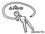
3) Connect the vacuum pump to the disconnected vacuum hoses.

SST: 5-8840-0279-0 - vacuum pump
4) Start and idle the engine for 10 seconds.
5) Perform the Turbocharger Solenoid with a scan tool.
6) Command the turbocharger control solenoid valve INCREASE/DECREASE. Does the vacuum pump indicate 50 cmHg {20 inHg} when INCREASE is maximum and does the value decline to 0 when DECREASE is minimum?
Yes
No
=>Go to Vacuum hose inspection.
6. Vacuum hose inspection
1) Inspect for the following. Is the result normal?
- Incorrect installation, disconnection, or twisting of the turbocharger control actuator vacuum hose
- Incorrect installation, disconnection, or twisting of the solenoid valve ventilation hose
- Incorrect installation, disconnection, or twisting of the vacuum hose
Yes
Replace the turbocharger control solenoid valve.
Refer to "1.Engine 1F.Induction(RZ4E-TC) turbocharger control solenoid valve removal".
Refer to "1.Engine 1F.Induction(RZ4E-TC) turbocharger control solenoid valve installation".
No
Repair or replace as necessary.
7. Repair verification
1) Reconnect all of the disconnected harness connectors and components.
2) If a DTC is set, clear the DTC with a scan tool.
3) Turn OFF the ignition switch for 30 seconds or more.
Procedure completion