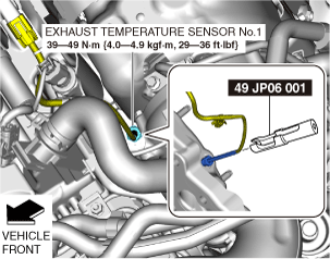
49 JP06 001
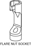
Exhaust gas temperature sensor wrench

EXHAUST GAS TEMPERATURE SENSOR REMOVAL/INSTALLATION [SKYACTIV-D 2.2]
id0140z7446400
Special Service Tool (SST)
|
49 JP06 001
Exhaust gas temperature sensor wrench
|
|
Exhaust Gas Temperature Sensor No.1 (Fuel injector (2pin type))
Replacement Part
|
Band
Quantity: 3
Location of use: Exhaust Gas Temperature Sensor No.5 (With SCR System)
|
Wiring harness clip band
Quantity: 1
Location of use: Exhaust Gas Temperature Sensor No.5 (With SCR System)
|
tape
Quantity: 1
Location of use: Exhaust Gas Temperature Sensor No.5 (With SCR System)
|
1. Disconnect the negative battery terminal. (See NEGATIVE BATTERY TERMINAL DISCONNECTION/CONNECTION.)
2. Remove the battery. (See BATTERY REMOVAL/INSTALLATION [SKYACTIV-D 2.2].)
3. Remove the air inlet pipe, air hose, and turbocharger air inlet hose. (See INTAKE-AIR SYSTEM REMOVAL/INSTALLATION [SKYACTIV-D 2.2].)
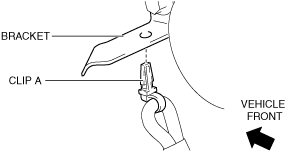
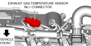
4. Disconnect the exhaust gas temperature sensor No.1 connector.
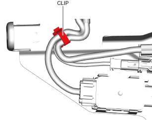
5. Remove the clip A from the bracket.
ac5wzw00007822
|
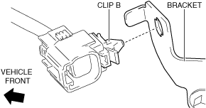
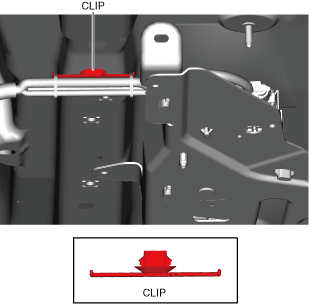
6. Remove the clip B from the bracket.
ac5wzw00007823
|
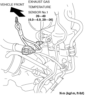
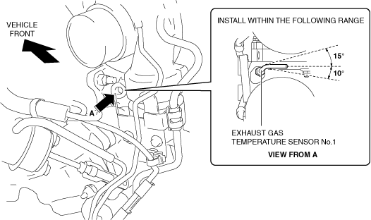
7. Remove the exhaust gas temperature sensor No.1. (See Exhaust gas temperature sensor No.1 installation note.)
ac5wzw00013712
|
ac5wzw00008481
|
8. Install in the reverse order of removal.
Exhaust gas temperature sensor No.1 installation note
1. Install the exhaust gas temperature sensor No.1 shown in the figure.
ac5wzw00008681
|
Exhaust Gas Temperature Sensor No.1 (Fuel Injector 6Pin Type)
1. Disconnect the negative battery terminal. (See NEGATIVE BATTERY TERMINAL DISCONNECTION/CONNECTION.)
2. Disconnect the exhaust gas temperature sensor No.1 connector.
ac5wzw00012069
|
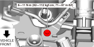
3. Remove the bolt shown in the figure.
ac5wzw00012070
|
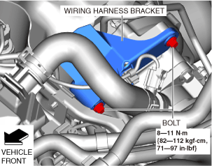
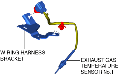
4. Set the wiring harness bracket out of the way.
ac5wzw00012071
|
5. Remove the exhaust gas temperature sensor No.1 and wiring harness bracket as single unit.
ac5wzw00012072
|
6. Remove the exhaust gas temperature sensor No.1.
ac5wzw00012073
|
7. Install in the reverse order of removal.
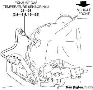
Exhaust Gas Temperature Sensor No.2 (Fuel injector (2pin type))
1. Disconnect the negative battery terminal. (See NEGATIVE BATTERY TERMINAL DISCONNECTION/CONNECTION.)
2. Remove the engine cover. (See ENGINE COVER REMOVAL/INSTALLATION [SKYACTIV-D 2.2].)
3. Remove the insulator. (See TIMING CHAIN REMOVAL/INSTALLATION [SKYACTIV-D 2.2].)
4. Disconnect the exhaust gas temperature sensor No.2 connector.
5. Remove the exhaust gas temperature sensor No.2. (See Exhaust gas temperature sensor No.2 installation note.)
ac5wzw00008682
|
6. Install in the reverse order of removal.
Exhaust gas temperature sensor No.2 installation note
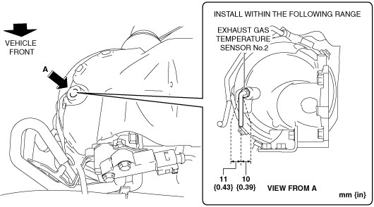
1. Install the exhaust gas temperature sensor No.2 shown in the figure.
ac5wzw00008683
|
Exhaust Gas Temperature Sensor No.2 (Fuel Injector (6Pin Type))
1. Disconnect the negative battery terminal. (See NEGATIVE BATTERY TERMINAL DISCONNECTION/CONNECTION.)
2. Remove the engine cover. (See ENGINE COVER REMOVAL/INSTALLATION [SKYACTIV-D 2.2].)
3. Turn the steering wheel completely to the right.
4. Lift up the vehicle.
5. Remove the front splash shield (RH). (See SPLASH SHIELD REMOVAL/INSTALLATION.)
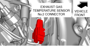
6. Disconnect the exhaust gas temperature sensor No.2 connector.
ac5wzw00012074
|
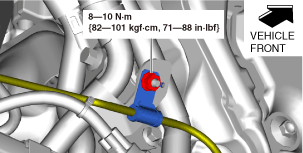
7. Remove the nut shown in the figure.
ac5wzw00012075
|
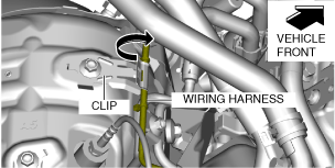
8. Set the wiring harness out of the way.
ac5wzw00012076
|
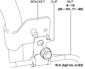
9. Remove the exhaust gas temperature sensor No.2.
ac5wzw00012077
|
10. Install in the reverse order of removal.
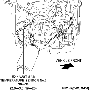
Exhaust Gas Temperature Sensor No.3 (Fuel Injector (2Pin Type)
ac5wzw00008684
|
1. Disconnect the negative battery terminal. (See NEGATIVE BATTERY TERMINAL DISCONNECTION/CONNECTION.)
2. Lift up the vehicle.
3. Remove the front under cover No.2. (See FRONT UNDER COVER No.2 REMOVAL/INSTALLATION.)
4. Remove the front splash shield (RH). (See SPLASH SHIELD REMOVAL/INSTALLATION.)
5. Disconnect the exhaust gas temperature sensor No.3 connector.
6. Remove the clip from the bracket.
ac5wzw00006396
|
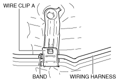
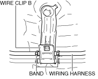
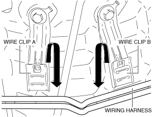
7. Remove the wiring harness from the wire clip A and B. (See Assembly of wiring harness to wire clip note.)
ac5wzw00006397
|
8. Remove the exhaust gas temperature sensor No.3.
ac5wzw00008685
|
9. Install in the reverse order of removal.
Assembly of wiring harness to wire clip note
ac5wzw00004450
|
ac5wzw00004451
|
Exhaust Gas Temperature Sensor No.3 (Fuel Injector (6Pin Type))
1. Disconnect the negative battery terminal. (See NEGATIVE BATTERY TERMINAL DISCONNECTION/CONNECTION.)
2. Turn the steering wheel completely to the right.
3. Lift up the vehicle.
4. Remove the front splash shield (RH). (See SPLASH SHIELD REMOVAL/INSTALLATION.)
5. Disconnect the exhaust gas temperature sensor No.3 connector.
ac5wzw00012078
|
6. Remove the exhaust gas temperature sensor No.3.
ac5wzw00012079
|
7. Install in the reverse order of removal.
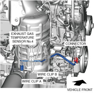
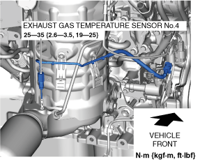
Exhaust Gas Temperature Sensor No.4 (With SCR System)
ac5wzw00012080
|
1. Disconnect the negative battery terminal. (See NEGATIVE BATTERY TERMINAL DISCONNECTION/CONNECTION.)
2. Remove the front under cover No.2. (See FRONT UNDER COVER No.2 REMOVAL/INSTALLATION.)
3. Remove the front splash shield (RH). (See SPLASH SHIELD REMOVAL/INSTALLATION.)
4. Remove the Insulator. (2WD) (See EXHAUST SYSTEM REMOVAL/INSTALLATION [SKYACTIV-D 2.2].)
5. Disconnect the exhaust gas temperature sensor No.4 connector.
6. Remove the wiring harness from the wire clip A and B. (See Assembly of wiring harness to wire clip note.)
ac5wzw00012081
|
7. Loosen the nuts (center bearing support) of the propeller shaft. (4WD) (See PROPELLER SHAFT REMOVAL/INSTALLATION.)
8. Disconnect the propeller shaft on the front side and set the propeller shaft onto the front crossmember. (4WD) (See PROPELLER SHAFT REMOVAL/INSTALLATION.)
9. Remove the exhaust gas temperature sensor No.4.
ac5wzw00012082
|
10. Install in the reverse order of removal.
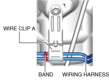
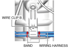
Assembly of wiring harness to wire clip note
ac5wzw00012083
|
ac5wzw00012084
|
Exhaust Gas Temperature Sensor No.5 (With SCR System)
1. Disconnect the negative battery terminal. (See NEGATIVE BATTERY TERMINAL DISCONNECTION/CONNECTION.)
2. Remove the floor under cover (LH). (4WD) (See FRONT UNDER COVER No.2 REMOVAL/INSTALLATION.)
3. Remove the floor under cover. (2WD) (See FRONT UNDER COVER No.2 REMOVAL/INSTALLATION.)
4. Remove the insulator and brace bar. (2WD) (See EXHAUST SYSTEM REMOVAL/INSTALLATION [SKYACTIV-D 2.2].)
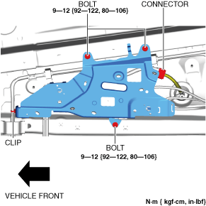
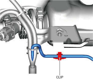
5. Remove the clip.
ac5wzw00012085
|
6. Remove the bolts.
7. Disconnect the connector.
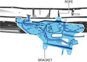
8. Suspend module bracket using a rope as shown in the figure.
ac5wzw00012086
|
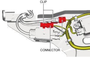
9. Disconnect the connectors.
ac5wzw00012087
|
10. Remove the clips.
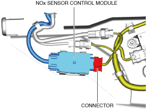
11. Disconnect the connector.
ac5wzw00012088
|
12. Remove the NOx sensor control module. (see NOx sensor control module removal note.)
13. Remove the clip.
ac5wzw00012089
|
14. Remove the clip.
ac5wzw00012090
|
15. Remove the clip.
ac5wzw00012091
|
16. Cut the bands. (See Band installation note.)
ac5wzw00012092
|
17. Cut the wiring harness clip band.
18. Remove the nut.
ac5wzw00012093
|
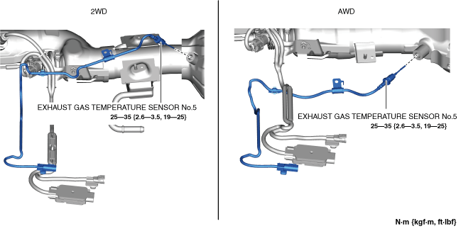
19. Remove the exhaust gas temperature sensor No.5.
ac5wzw00012094
|
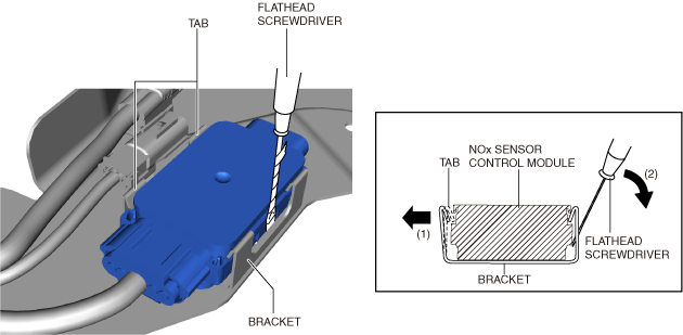
NOx sensor control module removal note
1. Insert a tape-wrapped flathead screwdriver into the position shown in the figure.
ac5wzw00012095
|
2. While moving the tab of the bracket in the direction of arrow (1), move the flathead screwdriver in the direction of arrow (2) and detach the bracket tabs from the NOx sensor control module.
3. Remove the NOx sensor control module.
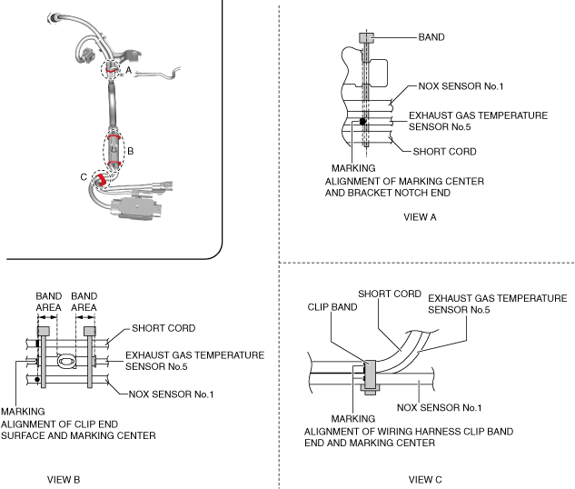
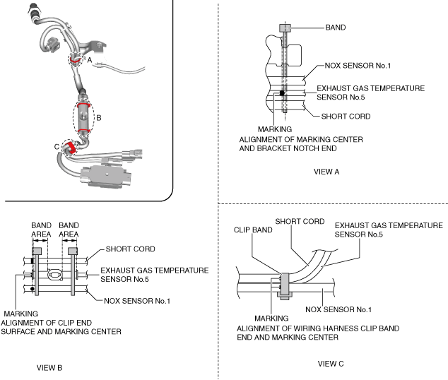
Band installation note
1. Install bands as shown in the figure.
2WD
ac5wzw00012096
|
4WD
ac5wzw00012097
|