 |
ac9uuw00008206
REAR BODY CONTROL MODULE (RBCM) INSPECTION
id094000002200
1. When replacing the rear body control module (RBCM), perform the configuration. (See REAR BODY CONTROL MODULE (RBCM) CONFIGURATION (USING READ/WRITE FUNCTION).)
2. Disconnect the negative battery terminal. (See NEGATIVE BATTERY TERMINAL DISCONNECTION/CONNECTION.)
3. Remove the following parts:
4. Remove the rear body control module (RBCM) from the body with the connector connected. (See REAR BODY CONTROL MODULE (RBCM) REMOVAL/INSTALLATION.)
5. Connect the negative battery terminal. (See NEGATIVE BATTERY TERMINAL DISCONNECTION/CONNECTION.)
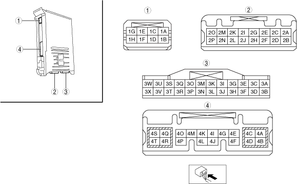
6. Verify that the voltages of each of the terminals are as indicated in the Terminal Voltage Table (Reference).
Terminal Voltage Table (Reference)
ac9uuw00008206
|
|
Terminal |
Signal |
Connected to |
Measurement conditions |
Voltage (V) |
Inspection item(s) |
|
|---|---|---|---|---|---|---|
|
1A*1
|
LIN communication ground
|
Intruder sensor
|
Under any condition
|
1.0 or less
|
• Intruder sensor
• Related wiring harness
|
|
|
1B
|
Interior light ground
|
• Front map light
• Rear map light
• Vanity mirror illumination (LH, RH)*2
|
Under any condition
|
1.0 or less
|
• Front map light
• Rear map light
• Vanity mirror illumination (LH, RH)*2
• Related wiring harness
|
|
|
1C
|
Foot light control
|
• Front foot light
• Rear foot light
|
LED ON
|
B+
|
• Front foot light
• Rear foot light
|
|
|
LED OFF
|
1.0 or less
|
|||||
|
1D
|
Down light control
|
• Console ambient light
|
LED ON
|
B+
|
• Console ambient light
|
|
|
LED OFF
|
1.0 or less
|
|||||
|
1E
|
Interior light control
|
• Front map light
|
Under any condition
|
1.0 or less
|
• Front map light
• Related wiring harness
|
|
|
1F
|
Interior light power supply
|
• Front map light
• Rear map light
• Vanity mirror illumination (LH, RH)*2
|
Under any condition
|
B+
|
• Front map light
• Rear map light
• Vanity mirror illumination (LH, RH)*2
• Related wiring harness
|
|
|
1G*1
|
LIN communication
|
Intruder sensor
|
Terminal used for communication therefore determination based on terminal voltage is not possible.
|
|||
|
1H*1
|
Power supply
|
Intruder sensor
|
Under any condition
|
B+
|
• Intruder sensor
• Related wiring harness
|
|
|
2A
|
—
|
—
|
—
|
—
|
—
|
|
|
2B
|
Power supply
|
D.LOCK 25 A fuse
|
Under any condition
|
B+
|
• D.LOCK 25 A fuse
• Related wiring harness
|
|
|
2C
|
Door lock control
|
Door lock actuator
|
Lock driver-side door lock switch from unlock
|
1.0 or less → B+→ 1.0 or less
|
• Door lock actuator
• Related wiring harness
|
|
|
Unlock driver-side door lock switch from lock
|
1.0 or less
|
|||||
|
2D
|
—
|
—
|
—
|
—
|
—
|
|
|
2E
|
Door unlock control
|
Door lock actuator
|
Unlock driver-side door lock switch from lock
|
1.0 or less → B+→ 1.0 or less
|
• Door lock actuator
• Related wiring harness
|
|
|
Lock driver-side door lock switch from unlock
|
1.0 or less
|
|||||
|
2F*1
|
Theft-deterrent horn relay control
|
Front body control module (FBCM)
|
Connected to M-MDS and using data monitor function, theft-deterrent sound activates
|
1.0 or less
|
• Front body control module (FBCM)
• Related wiring harness
|
|
|
Connected to M-MDS and using data monitor function, theft-deterrent sound does not activate
|
B+
|
|||||
|
2G
|
Double locking system control
|
Door lock actuator
|
Press transmitter lock button two times (double locking system operation condition)
|
B+→ 1.0 or less
|
• Door lock actuator
• Related wiring harness
|
|
|
Except above
|
1.0 or less
|
|||||
|
2H
|
Brake light control
|
• Brake light relay
• Brake light unit*3
|
Connect the M-MDS and turn on the “STOP_LMP_CS” using the rear body control module (RBCM) simulation function
|
1.0 or less
|
• Brake light relay
• Brake light unit*3
• Related wiring harness
|
|
|
Connect the M-MDS and turn off the “STOP_LMP_CS” using the rear body control module (RBCM) simulation function
|
B+
|
|||||
|
2I
|
Ignition power supply
|
METER1 10 A fuse
|
Ignition switched ON (engine off)
|
B+
|
• METER1 10 A fuse
• Related wiring harness
|
|
|
Ignition switched OFF (LOCK)
|
1.0 or less
|
|||||
|
2J
|
Brake switch signal
|
• Start stop unit
• Brake switch
|
Brake pedal depressed
|
B+
|
• Start stop unit
• Brake switch
• Related wiring harness
|
|
|
Brake pedal not depressed
|
1.0 or less
|
|||||
|
2K*4
|
Rear fog light power supply
|
STOP 10 A fuse
|
Under any condition
|
B+
|
• STOP 10 A fuse
• Related wiring harness
|
|
|
2L
|
—
|
—
|
—
|
—
|
—
|
|
|
2M
|
Power supply
|
R.WIPER 15 A fuse
|
Under any condition
|
B+
|
• R.WIPER 15 A fuse
• Battery
• Related wiring harness
|
|
|
2N
|
—
|
—
|
—
|
—
|
—
|
|
|
2O
|
—
|
—
|
—
|
—
|
—
|
|
|
2P
|
Power supply
|
ROOM 15 A fuse
|
Under any condition
|
B+
|
• ROOM 15 A fuse
• Related wiring harness
|
|
|
3A*1
|
LIN communication
|
Theft-deterrent siren
|
Terminal used for communication therefore determination based on terminal voltage is not possible.
|
|||
|
3B
|
Serial communication
|
Start stop unit
|
Terminal used for communication therefore determination based on terminal voltage is not possible.
|
|||
|
3C
|
Fuel sensor ground
|
Fuel gauge sender unit
|
Under any condition
|
1.0 or less
|
• Fuel gauge sender unit
• Related wiring harness
|
|
|
3D
|
Serial communication
|
Power window main switch
|
Terminal used for communication therefore determination based on terminal voltage is not possible.
|
|||
|
3E
|
CAN_H
|
CAN system related module
|
Terminal used for communication therefore determination based on terminal voltage is not possible.
|
|||
|
3F
|
Door lock switch signal
|
Door lock switch
|
Door lock switch unlocked
|
1.0 or less
|
• Door lock switch
• Related wiring harness
|
|
|
Other
|
4.5
|
|||||
|
Door lock switch locked
|
2.2
|
|||||
|
3G
|
CAN_L
|
CAN system related module
|
Terminal used for communication therefore determination based on terminal voltage is not possible.
|
|||
|
3H
|
Driver-side door key cylinder switch signal
|
Door key cylinder switch
|
Door key cylinder is turned to unlock side
|
1.0 or less
|
• Door key cylinder switch
• Related wiring harness
|
|
|
Other
|
4.5
|
|||||
|
Door key cylinder is turned to lock side
|
2.2
|
|||||
|
3I
|
Fuel sensor signal
|
Fuel gauge sender unit
|
Inspect the fuel gauge sender unit and related wiring harnesses because the terminal voltage at this terminal cannot be examined.
|
|||
|
3J
|
Lock input (lock-link switch (passenger's side, rear door))
|
• Door lock-link switch
• Power liftgate (PLG) control module
|
The passenger-side and rear doors are all locked
|
4.6
|
• Door lock-link switch
• Power liftgate (PLG) control module
• Related wiring harness
|
|
|
Among the passenger-side and rear doors, at least one door is unlocked
|
1.0 or less
|
|||||
|
3K*5
|
Fuel sensor signal (sub)
|
Fuel gauge sender unit (sub)
|
Inspect the fuel gauge sender unit and related wiring harnesses because the terminal voltage at this terminal cannot be examined.
|
|||
|
3L*6
|
Bonnet latch switch signal
|
Bonnet latch switch
|
Bonnet open
(Bonnet latch switch OFF)
|
4.6
|
• Bonnet latch switch
• Related wiring harness
|
|
|
Bonnet is closed
(Bonnet latch switch ON)
|
1.0 or less
|
|||||
|
3M
|
Unlock input (front door lock-link switch (driver's door))
|
• Door lock-link switch (driver's door)
• Power liftgate (PLG) control module
|
Driver's door locked
|
4.6
|
• Door lock-link switch (driver's door)
• Power liftgate (PLG) control module
• Related wiring harness
|
|
|
Driver's door unlocked
|
1.0 or less
|
|||||
|
3N
|
—
|
—
|
—
|
—
|
—
|
|
|
3O
|
Lock input (front door lock-link switch (driver's door))
|
• Door lock-link switch (driver's door)
• Start stop unit
• Power liftgate (PLG) control module
|
Driver's door locked
|
1.0 or less
|
• Door lock-link switch (driver's door)
• Start stop unit
• Power liftgate (PLG) control module
• Related wiring harness
|
|
|
Driver's door unlocked
|
4.6
|
|||||
|
3P
|
—
|
—
|
—
|
—
|
—
|
|
|
3Q
|
Rear door switch (RH) signal
|
Door latch switch (RR)
|
Rear door (RH) open
|
1.0 or less
|
• Rear door switch (RH)
• Related wiring harness
|
|
|
Rear door (RH) closed
|
B+
|
|||||
|
3R
|
Serial communication
|
• SAS control module
• Mazda era-glonass control module*7
|
Terminal used for communication therefore determination based on terminal voltage is not possible.
|
|||
|
3S
|
Rear door switch (LH) signal
|
Door latch switch (LR)
|
Rear door (LH) open
|
1.0 or less
|
• Rear door switch (LH)
• Related wiring harness
|
|
|
Rear door (LH) closed
|
B+
|
|||||
|
3T
|
Rear buckle switch (RH) power supply
|
Rear buckle switch (RH)
|
Ignition switched ON (engine off)
|
Insert rear seat belt (RH) into buckle
|
B+
|
• Rear buckle switch (RH)
• Related wiring harness
|
|
Rear seat belt (RH) not inserted into buckle
|
1.0 or less
|
|||||
|
3U
|
Front door switch (passenger's door) signal
|
Door latch switch (passenger's door)
|
Front door (passenger's door) open
|
1.0 or less
|
• Front door switch (passenger's door)
• Related wiring harness
|
|
|
Front door (passenger's door) closed
|
B+
|
|||||
|
3V
|
Rear center buckle switch power supply
|
Rear center buckle switch
|
Ignition switched ON (engine off)
|
Insert rear seat belt (center) into buckle
|
B+
|
• Rear center buckle switch
• Related wiring harness
|
|
Rear seat belt (center) not inserted into buckle
|
1.0 or less
|
|||||
|
3W
|
Front door switch (driver's door) signal
|
Door latch switch (driver's door)
|
Front door (driver's door) open
|
1.0 or less
|
• Front door switch (driver's door)
• Related wiring harness
|
|
|
Front door (driver's door) closed
|
B+
|
|||||
|
3X
|
Rear buckle switch (LH) power supply
|
Rear buckle switch (LH)
|
Ignition switched ON (engine off)
|
Insert rear seat belt (LH) into buckle
|
B+
|
• Rear buckle switch (LH)
• Related wiring harness
|
|
Rear seat belt (LH) not inserted into buckle
|
1.0 or less
|
|||||
|
4A
|
Rear window wiper motor power supply
|
Rear wiper motor
|
Ignition switched ON (engine off)
|
B+
|
• Rear wiper motor
• Related wiring harness
|
|
|
Ignition switched OFF (LOCK)
|
1.0 or less
|
|||||
|
4B
|
Power ground
|
Body ground
|
Under any condition
|
1.0 or less
|
• Related wiring harness
|
|
|
4C
|
Liftgate latch and lock actuator
|
Liftgate latch and lock actuator
|
Press liftgate opener switch
|
B+→ 1.0 or less
|
• Liftgate latch and lock actuator
• Related wiring harness
|
|
|
Except above
|
1.0 or less
|
|||||
|
4D
|
Brake light control
|
• Brake light unit*3
• Brake light relay
|
Brake pedal depressed
|
B+
|
• Brake light unit*3
• Brake light relay
• Related wiring harness
|
|
|
Brake pedal not depressed
|
1.0 or less
|
|||||
|
4E
|
—
|
—
|
—
|
—
|
—
|
|
|
4F
|
Cargo compartment light power supply
|
Cargo compartment light
|
Under any condition
|
B+
|
• Cargo compartment light
• Related wiring harness
|
|
|
4G
|
CAN_H
|
CAN system related module
|
Terminal used for communication therefore determination based on terminal voltage is not possible.
|
|||
|
4H
|
—
|
—
|
—
|
—
|
—
|
|
|
4I
|
CAN_H
|
CAN system related module
|
Terminal used for communication therefore determination based on terminal voltage is not possible.
|
|||
|
4J
|
CAN_L
|
CAN system related module
|
Terminal used for communication therefore determination based on terminal voltage is not possible.
|
|||
|
4K
|
Liftgate latch switch signal
|
Liftgate latch and lock actuator
|
Liftgate open
|
1.0 or less
|
• Liftgate latch and lock actuator
• Related wiring harness
|
|
|
Liftgate closed
|
B+
|
|||||
|
4L
|
CAN_L
|
CAN system related module
|
Terminal used for communication therefore determination based on terminal voltage is not possible.
|
|||
|
4M
|
Liftgate opener switch signal
|
Liftgate opener switch
Power liftgate (PLG) control module
|
Liftgate opener switch pressed
|
1.0 or less
|
• Liftgate opener switch
• Power liftgate (PLG) control module
• Related wiring harness
|
|
|
Liftgate opener switch not pressed
|
4.5
|
|||||
|
4N
|
—
|
—
|
—
|
—
|
—
|
|
|
4O
|
—
|
—
|
—
|
—
|
—
|
|
|
4P
|
Cargo compartment light control
|
Cargo compartment light
|
Liftgate open
|
1.0 or less
|
• Cargo compartment light
• Related wiring harness
|
|
|
Liftgate closed
|
B+
|
|||||
|
4Q*4
|
Rear fog light control
|
Rear fog light
|
Light switch at TNS position
|
Rear fog light at OFF
|
1.0 or less
|
• Rear fog light
• Related wiring harness
|
|
Rear fog light at ON
|
B+
|
|||||
|
4R
|
Signal ground
|
Body ground
|
Under any condition
|
1.0 or less
|
• Related wiring harness
|
|
|
4S
|
Back-up light control
|
• Back-up light (LH, RH)
• Auto dimming rear view mirror
|
Ignition switched ON (engine off)
|
Selector lever at R position
|
B+
|
• Back-up light switch
• Auto dimming rear view mirror
• Related wiring harness
|
|
Other
|
1.0 or less
|
|||||
|
4T
|
Rear wiper motor control (LO)
|
Rear wiper motor
|
Rear wiper switch at ON
|
1.0 or less
|
• Rear wiper motor
• Related wiring harness
|
|
|
Rear wiper switch at OFF
|
B+
|
|||||