acxaaw00001481
|
PARKING BRAKE REMOVAL/INSTALLATION [ATX (4WD)]
id0412008002a8
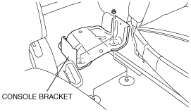
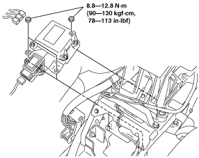
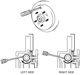
1. Perform the following procedure and remove the parking brake pedal.
2. Perform the following procedure and remove the front parking brake cable.
acxaaw00001481
|
acxaaw00001482
|
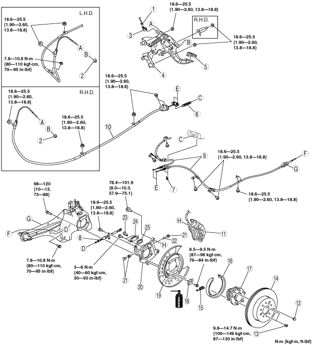
3. Perform the following procedure and remove the rear parking brake cable.
4. Perform the following procedure and remove the parking brake plate, back plate and wheel hub.
5. Remove in the order indicated in the table.
6. Install in the reverse order of removal.
7. Adjust the parking brake stroke. (See PARKING BRAKE ADJUSTMENT [ATX].)
8. Inspect the rear wheel alignment. (See REAR WHEEL ALIGNMENT.)
acxaaw00001594
|
|
1
|
Parking brake switch connector
|
|
2
|
Adjusting nut
|
|
3
|
Parking brake switch
|
|
4
|
Parking brake pedal
|
|
5
|
Parking brake pedal pad
|
|
6
|
Spring
|
|
7
|
Clip
|
|
8
|
End cable
(See End Cable Removal Note.)
(See End Cable Installation Note.)
|
|
9
|
Rear parking brake cable
|
|
10
|
Front Parking brake cable, equalizer
|
|
11
|
Brake caliper component
|
|
12
|
Plug
|
|
13
|
Screw
|
|
14
|
Disc plate
(See Disc Plate Removal Note.)
|
|
15
|
Spring
|
|
16
|
Parking brake shoe
|
|
17
|
Rear wheel hub component
|
|
18
|
Shoe stopper
|
|
19
|
Backing plate
|
|
20
|
Parking brake plate
|
|
21
|
Adjuster bolt and nut, tappet
|
|
22
|
Pin
|
|
23
|
Operation lever
|
|
24
|
Plate
|
|
25
|
Dust boot
|
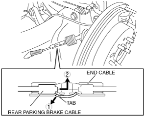
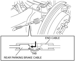
End Cable Removal Note
1. Remove the end cable installation bolts.
2. Disconnect the end cable from the operation lever.
3. Bend the end cable tab (rear parking brake cable side) in the direction shown in the figure.
acxaaw00001484
|
4. Move the rear parking brake cable end in the direction shown in the figure and disconnect it from the end cable.
5. Remove the end cable.
Brake Caliper Component Removal Note
1. Remove the brake caliper assembly from the trailing link and suspend it with a cable so it does not interfere.
Disc Plate Removal Note
1. If any disc plate is difficult to remove, perform the following steps to remove it.
acxaaw00001485
|
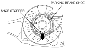
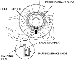
Parking Brake Shoe Removal Note
1. Pull the parking brake shoe downward and disengage it from the shoe stopper.
acxaaw00001486
|
2. Press the adjuster bolt and tappet by hand, and slowly remove the parking brake shoe.
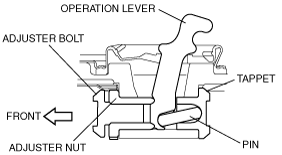
Operation lever, Pin, Adjuster Bolt and Nut, Tappet Installation Note
1. Install the operation lever, pin, adjuster bolt and nut, and tappet so that the adjuster nut is facing toward the vehicle front.
acxaaw00001487
|
2. Completely tighten the adjuster bolt and nut.
3. Move the operation lever by hand and verify that it operates properly.
Parking Brake Shoe Installation Note
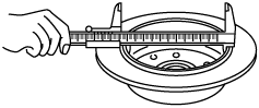
1. Measure the parking brake lining thickness with a vernier caliper or measuring scale.
acxaaw00001488
|
2. Apply grease to the contact face of the parking brake shoe and the shoe stopper.
3. After installing the opening of the parking brake shoe to the adjuster bolt and tappet, push the brake shoe upward and attach it to the shoe stopper.
acxaaw00001489
|
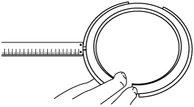
Disc Plate, Screw Installation Note
1. Measure the inner diameter of the disc plate with a vernier caliper.
acxaaw00001490
|
2. Install the disc plate and screw.
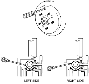
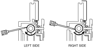
3. Perform the following steps to adjust the shoe clearance after installing the disc plate and the screws.
acxaaw00001491
|
acxaaw00001375
|
End Cable Installation Note
1. Move the rear parking brake cable end in the direction shown in the figure and install it to the end cable.
acxaaw00001492
|
2. Verify that the end cable tab (rear parking brake cable side) is attached properly to the rear parking brake cable end.
3. Install the end cable to the operation lever.
4. Install the end cable installation bolts.
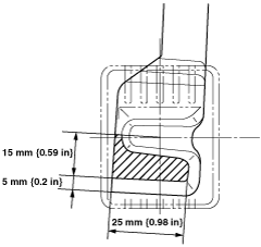
Parking Brake Pedal Pad Installation Note
1. Degrease the parking brake pedal pad installation surface of the parking brake pedal.
2. Apply commercially available instant adhesive to the area (shaded area) shown in the figure of the parking brake pedal and install the parking brake pedal pad.
am8rrw00002657
|