1. : Mazda SST number
2. : Global SST number
1: 49 UN30 3050
2: 303–050
Engine lifting bracket

1: 49 L017 5A0
2: –
Support hanger

ENGINE DISASSEMBLY/ASSEMBLY [SKYACTIV-D 2.2]
id0110s5800500
Special Service Tool (SST)
|
1. : Mazda SST number
2. : Global SST number
|
|||
|
1: 49 UN30 3050
2: 303–050
Engine lifting bracket
|
|
1: 49 L017 5A0
2: –
Support hanger
|
|
Replacement Part
|
Gasket
Quantity: 2
Location of use: Water pipe A
|
Gasket
Quantity: 1
Location of use: Water pipe B
|
Bolt
Quantity: 2
Location of use: Noise suppression cover (No.3)
|
|
Gasket
Quantity: 1
Location of use: Oil pipe
|
Air hose
Quantity: 2
Location of use: Exhaust gas pressure sensor No.2
|
Clip
Quantity: 2
Location of use: Exhaust gas pressure sensor No.2
|
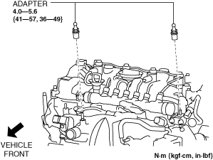
1. Remove the adapter.
ac8wzw00002490
|
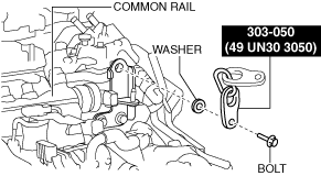
2. Install the SST to the position shown in the figure using the following bolt and washer.
ac5wzw00006602
|
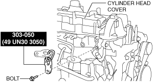
3. Install the SST to the position shown in the figure using the following bolt.
ac5wzw00006603
|
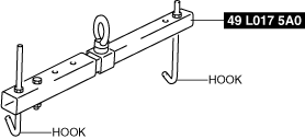
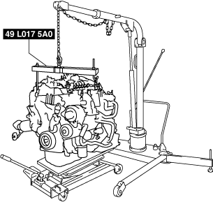
4. Engage the hooks of the SST (49 L017 5A0) to the SST (49 UN30 3050).
ac5wzw00005215
|
5. To ensure the safety of the work (control engine and transaxle sway), set a hoist as shown in the figure.
ac5jjw00005202
|
6. Remove the catalytic converter. (See EXHAUST SYSTEM REMOVAL/INSTALLATION [SKYACTIV-D 2.2].)
7. Remove the transfer bracket and transfer. (4WD) (See TRANSFER REMOVAL/INSTALLATION [GW6AX-EL].)
8. Remove the turbocharger. (See TURBOCHARGER REMOVAL/INSTALLATION [SKYACTIV-D 2.2].)
9. Remove the exhaust gas temperature sensor No.1. (See EXHAUST GAS TEMPERATURE SENSOR REMOVAL/INSTALLATION [SKYACTIV-D 2.2].)
10. Remove the exhaust gas pressure sensor No.1 component. (See EXHAUST SYSTEM REMOVAL/INSTALLATION [SKYACTIV-D 2.2].)
11. Remove the exhaust manifold. (See EXHAUST SYSTEM REMOVAL/INSTALLATION [SKYACTIV-D 2.2].)
12. Remove the following emission system related parts:
13. Remove the bracket No.1. (See FRONT DRIVE SHAFT REMOVAL/INSTALLATION.)
14. Remove the starter. (See STARTER REMOVAL/INSTALLATION [SKYACTIV-D 2.2].)
15. Remove the generator. (See GENERATOR REMOVAL/INSTALLATION [SKYACTIV-D 2.2].)
16. Remove the drive belt auto tensioner. (See DRIVE BELT AUTO TENSIONER REMOVAL/INSTALLATION [SKYACTIV-D 2.2].)
17. Remove the water pump, water pump housing and coolant control valve as a single unit. (See COOLANT CONTROL VALVE REMOVAL/INSTALLATION [SKYACTIV-D 2.2].)
18. Remove the thermo valve. (See THERMO VALVE REMOVAL/INSTALLATION [SKYACTIV-D 2.2].)
19. Lock the drive plate against rotation using the crankshaft pulley lock bolt.
20. Remove the torque converter installation nut from the starter installation hole. (See AUTOMATIC TRANSAXLE REMOVAL/INSTALLATION [GW6A-EL] (2WD).) (See AUTOMATIC TRANSAXLE REMOVAL/INSTALLATION [GW6AX-EL] (4WD).)
21. Disconnect the engine and transaxle, and lower only the engine from the engine lifter. (See AUTOMATIC TRANSAXLE REMOVAL/INSTALLATION [GW6A-EL] (2WD).) (See AUTOMATIC TRANSAXLE REMOVAL/INSTALLATION [GW6AX-EL] (4WD).)
22. Remove the intake-air system. (See INTAKE-AIR SYSTEM REMOVAL/INSTALLATION [SKYACTIV-D 2.2].)
23. Remove the following fuel system related parts:
24. Remove the glow plugs. (See GLOW PLUG REMOVAL/INSTALLATION [SKYACTIV-D 2.2].)
25. Remove the vacuum pump. (See VACUUM PUMP REMOVAL/INSTALLATION [SKYACTIV-D 2.2].)
26. Remove the oil cooler. (See OIL COOLER REMOVAL/INSTALLATION [SKYACTIV-D 2.2].)
27. Remove the oil filter. (See OIL FILTER REPLACEMENT [SKYACTIV-D 2.2].)
28. Remove the engine oil solenoid valve. (See ENGINE OIL SOLENOID VALVE REMOVAL/INSTALLATION [SKYACTIV-D 2.2].)
29. Remove the following control system related parts:
30. Remove the short cord of the engine oil level sensor. (See ENGINE OIL LEVEL SENSOR REMOVAL/INSTALLATION [SKYACTIV-D 2.2].)
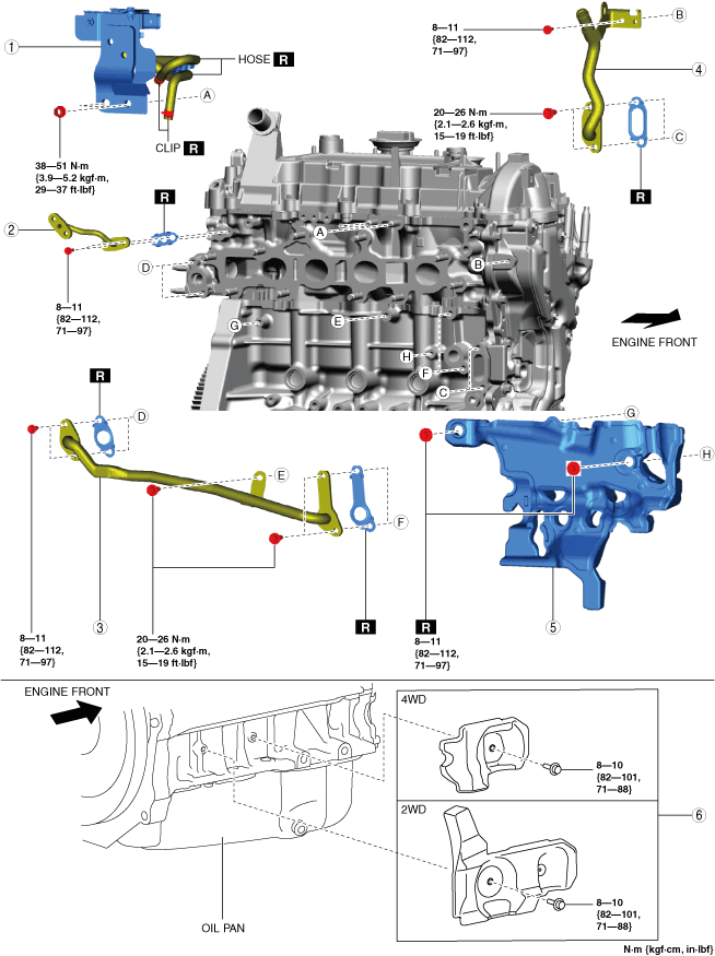
31. Disassemble in the order indicated in the table.
32. Assemble in the reverse order of disassembly.
Step 1
ac8wzw00004295
|
|
1
|
Exhaust gas pressure sensor No.2 component
|
|
2
|
Oil pipe (cylinder head side)
|
|
3
|
Water pipe A
|
|
4
|
Water pipe B
|
|
5
|
Noise suppression cover (No.3)
|
|
6
|
Seal rubber
|
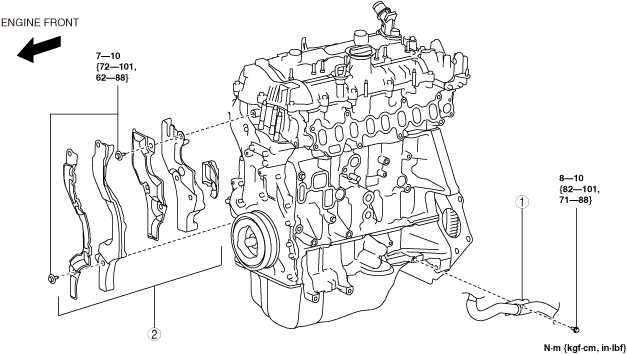
Step 2
ac8wzw00002492
|
|
1
|
Water hose
|
|
2
|
Noise suppression cover (No.1), noise suppression cover (No.2), seal rubber
|
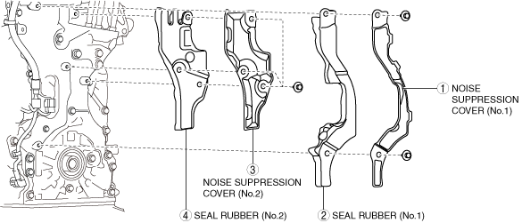
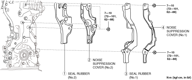
Noise Suppression Cover (No.1), Noise Suppression Cover (No.2), Seal Rubber Removal Note
1. Remove the noise suppression covers and seal rubbers in the order shown in the figure.
ac5uuw00008415
|
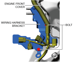
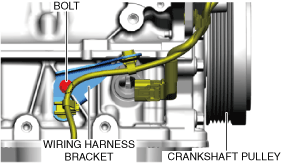
2. Remove the wiring harness using the following procedure:
ac8wzw00002493
|
ac5uuw00008417
|
3. Remove the seal rubber (No.3).
ac8wzw00002494
|
Noise Suppression Cover (No.1), Noise Suppression Cover (No.2), Seal Rubber Installation Note
1. Temporarily put the seal rubber (No.3) on the engine front cover.
ac8wzw00002494
|
2. Install the wiring harness and wiring harness bracket using the following procedure:
ac8wzw00002493
|
ac5uuw00008417
|
3. Install the noise suppression covers and seal rubbers in the order shown in the figure.
ac5uuw00008418
|