AUTOMATIC TRANSAXLE REMOVAL/INSTALLATION [GW6A-EL]
id0517i21172i1
Special service tool (SST)
|
Mazda and Ford SST numbers can be referenced. Ford manufactured SSTs are as follows:
-
1. : Mazda SST number
2. : Ford SST number
|
|
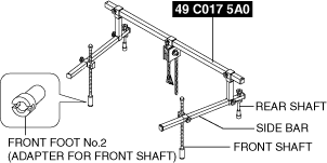
1: 49 C017 5A0
2:–
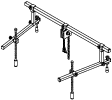
Engine support set
|
 |
1:49 UN30 3050
2:303-050
Engine lifting bracket
|
 |
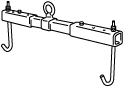
1:49 L017 5A0
2:–
Support hanger
|
 |
Replacement Part
|
washer
Quantity: 1
Location of use: plug
|
-
Caution
-
• Performing the following procedures could cause an open circuit in the front ABS wheel-speed sensor wiring harness if it is pulled by mistake. Before servicing, disconnect the front ABS wheel-speed sensor and set it aside so that the wiring harness will not be pulled by mistake.
• If the steering wheel rotates after the steering shaft and the steering gear and linkage are disconnected, the internal parts of the clock spring could be damaged. After disconnecting the steering shaft, secure the steering wheel using tape or cable to prevent it from rotating.
Removal
1. Disconnect the negative battery terminal. (See NEGATIVE BATTERY TERMINAL DISCONNECTION/CONNECTION.)
2. Remove the following parts as a single unit. (See INTAKE-AIR SYSTEM REMOVAL/INSTALLATION [SKYACTIV-D 2.2].)
-
• Air cleaner cover
• Air cleaner element
• Fresh-air duct
• Air cleaner case
• Air hose
• Resonance chamber
3. Remove the battery and the battery tray. (See BATTERY REMOVAL/INSTALLATION [SKYACTIV-D 2.2].)
4. Remove the front splash shield. (See SPLASH SHIELD REMOVAL/INSTALLATION.)
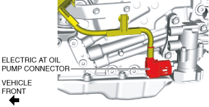
5. Disconnect the electric AT oil pump connector.
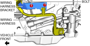
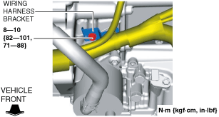
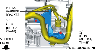
6. Remove the bolts and set the wiring harness and wiring harness bracket in a place which does not interfere with servicing.
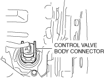
7. Disconnect the control valve body connector.
-
Caution
-
• Be careful that your hand does not touch the terminal as the connector terminal could be damaged.
• Do not allow foreign matter or water to penetrate the connector. Otherwise, it could cause poor contact and corrosion.
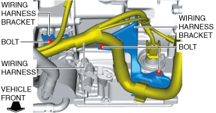
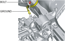
8. Remove the bolts and set the wiring harness and wiring harness bracket in a place which does not interfere with servicing.
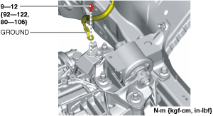
9. Disconnect the ground.
10. Disconnect the selector cable from the transaxle. (See SELECTOR CABLE REMOVAL/INSTALLATION.)
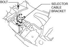
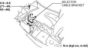
11. Remove the selector cable bracket.
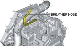
12. Disconnect the breather hose from the transaxle.
13. Remove the joint cover. (See STEERING WHEEL AND COLUMN REMOVAL/INSTALLATION.)
14. Disconnect the intermediate shaft from the steering gear and linkage. (See STEERING WHEEL AND COLUMN REMOVAL/INSTALLATION.)
15. Remove the engine cover. (See ENGINE COVER REMOVAL/INSTALLATION [SKYACTIV-D 2.2].)
16. Remove the air inlet pipe. (See INTAKE-AIR SYSTEM REMOVAL/INSTALLATION [SKYACTIV-D 2.2].)
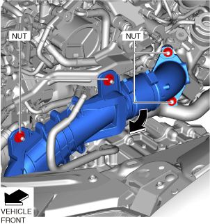
17. Remove the nuts and set the turbocharger air outlet pipe component aside in the direction of the arrow shown in the figure. (See INTAKE-AIR SYSTEM REMOVAL/INSTALLATION [SKYACTIV-D 2.2].)
18. Drain the engine coolant. (See ENGINE COOLANT REPLACEMENT [SKYACTIV-D 2.2].)
19. Set the water pipe component aside. (See EGR COOLER REMOVAL/INSTALLATION [SKYACTIV-D 2.2].)
20. Remove the EGR pipe (EGR valve side). (See EGR PIPE REMOVAL/INSTALLATION [SKYACTIV-D 2.2].)
21. Remove the EGR cooler. (See EGR COOLER REMOVAL/INSTALLATION [SKYACTIV-D 2.2].)
22. Remove the front tires. (See WHEEL AND TIRE REMOVAL/INSTALLATION.)
23. Remove front under cover No.2. (See FRONT UNDER COVER No.2 REMOVAL/INSTALLATION.)
24. Remove front under cover No.1. (See FRONT UNDER COVER No.1 REMOVAL/INSTALLATION.)
25. Drain the ATF. (See AUTOMATIC TRANSAXLE FLUID (ATF) REPLACEMENT [GW6A-EL, GW6AX-EL].)
26. Disconnect the oil cooler from the transaxle with the hose connected. (Except for automatic transaxle replacement) (See OIL COOLER REMOVAL/INSTALLATION [GW6A-EL, GW6AX-EL].)
27. Disconnect the water hose from the oil cooler. (Automatic transaxle replacement) (See OIL COOLER REMOVAL/INSTALLATION [GW6A-EL, GW6AX-EL].)
28. Remove the starter. (See STARTER REMOVAL/INSTALLATION [SKYACTIV-D 2.2].)
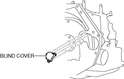
29. Remove the blind cover.
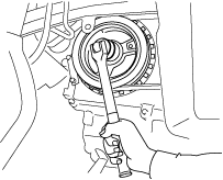
30. Secure the crankshaft pulley so that the torque converter does not rotate.
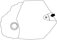
31. Remove the torque converter installation nuts from the starter installation hole.
-
Note
-
• There are six installation nuts.
32. Disconnect the front ABS wheel-speed sensor from the steering knuckle. (See FRONT ABS WHEEL-SPEED SENSOR REMOVAL/INSTALLATION.)
33. Disconnect the brake hose clip from the front shock absorber. (See FRONT BRAKE HOSE REMOVAL/INSTALLATION.)
34. Disconnect the tie-rod end from the steering knuckle. (See TIE-ROD END REPLACEMENT.)
35. Disconnect the front lower arm from the steering knuckle. (See FRONT LOWER ARM REMOVAL/INSTALLATION.)
36. Disconnect the front stabilizer control link from the front stabilizer. (See FRONT STABILIZER REMOVAL.)
37. Disconnect the front drive shaft (LH) from the transaxle. (See FRONT DRIVE SHAFT REMOVAL/INSTALLATION.)
38. Disconnect the front drive shaft (RH) from the transaxle. (See FRONT DRIVE SHAFT REMOVAL/INSTALLATION.)
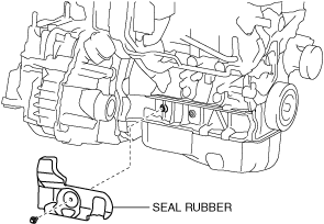
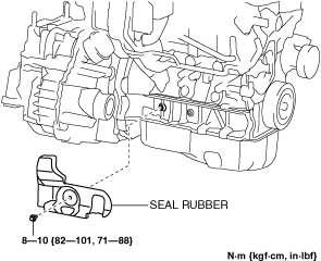
39. Remove the seal rubber.
40. Remove the front crossmember component and No.1 engine mount rubber as a single unit. (See FRONT CROSSMEMBER REMOVAL/INSTALLATION.)
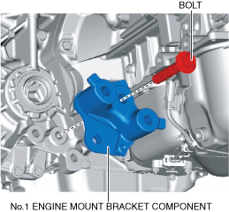
41. Remove the No.1 engine mount bracket component from the transaxle.
42. Install the SST using the following procedure.
-
Caution
-
• For the basic operation of the SST, refer to the instruction manual included with the SST.
- (1) Install the front foot No.2 to the left and right front shafts of the SST.
-
- (2) Protect the position shown in the figure using protective tape.
-
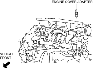
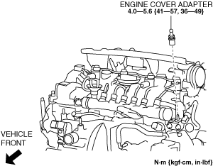
- (3) Remove the engine cover adapter.
-
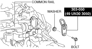
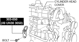
- (4) Install the SST to the position shown in the figure using the following bolt and washer.
-
Engine front side
-
Bolt: Part number 99794 1025 or M10 × 1.25 (length 25 mm {0.98 in})
-
Washer: Thickness 3 mm {0.1 in}
-
Tightening torque
-
38—51 N·m {3.9—5.2 kgf·m, 29—37 ft·lbf}
Engine rear side
-
Bolt: Part number 99794 1025 or M10 × 1.25 (length 25 mm {0.98 in})
-
Tightening torque
-
38—51 N·m {3.9—5.2 kgf·m, 29—37 ft·lbf}
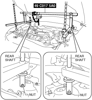
- (5) Set the rear shafts of the SST on the left/right front shock absorber nuts as shown in the figure.
-
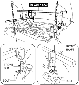
- (6) Set the front shafts of the SST to the bolts as shown in the figure.
-
- (7) Install the SST (49 L017 5A0) to the SST (49 C017 5A0) as shown in the figure.
-
- (8) Install the SST (49 L017 5A0) to the SST (49 UN30 3050) with the hook of the SST (49 L017 5A0) facing outward.
-
- (9) Adjust the height of the left and right side bars of the SST so that they are leveled, then tighten each part of the SST.
-
- (10) Apply tension to the chain to support the engine and verify that the engine is securely hung.
-
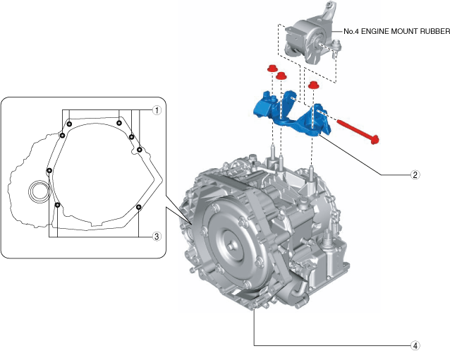
43. Remove using the procedure shown in the figure.
-
Warning
-
• Be careful that the transaxle does not fall off the transmission jack.
-
Caution
-
• Remove the transaxle while being careful not to tilt it towards the torque converter so that they do not separate.
|
1
|
Transaxle installation bolt (upper)
|
|
2
|
No.4 engine mount bracket
|
|
3
|
Transaxle installation bolt (lower)
|
|
4
|
Transaxle
|
No.4 engine mount bracket removal note
-
Caution
-
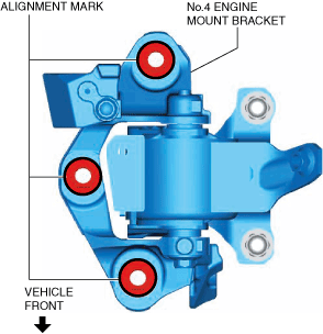
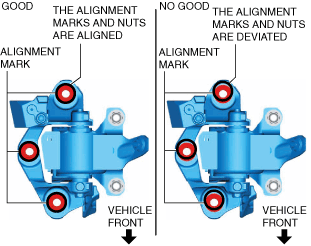
• Slots have been adopted for the No.4 engine mount bracket installation holes. If the No.4 engine mount bracket deviates from its original position when it is installed, engine noise or vibration could increase. When installing the No.4 engine mount bracket, align it to the alignment marks placed during removal and install it to its original position.
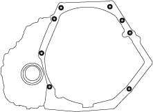
1. Place alignment marks at the positions shown in the figure so that they can be assembled to the same positions as before removal.
-
Note
-
• Place the alignment marks so that the contour of the nuts on the bracket side are outlined.
2. Remove the No.4 engine mount bracket.
Transaxle installation bolt removal note
-
Warning
-
• Carefully remove the transaxle while keeping it stable. Otherwise, it may fall off and cause damage or injury.
1. Adjust the SST (49 C017 5A0) and tilt the engine towards the transaxle side.
2. Support the transaxle using the transmission jack.
3. Remove the transaxle installation bolts (lower).
4. Remove the transaxle.
Installation
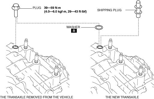
1. If the transaxle is replaced with a new one, perform the following procedure.
- (1) Remove the shipping plug from the new transaxle.
-
- (2) Remove the plug from the transaxle removed from the vehicle.
-
- (3) Install the plug and washer that were removed to the new transaxle.
-
-
Caution
-
• Install the transaxle installation bolts after verifying that the torque converter stud bolt passes through the drive plate bolt hole. Otherwise, the drive plate could be damaged.
2. Verify that the torque converter stud bolt passes through the drive plate bolt hole from the starter installation hole.
3. Tighten the transaxle installation bolts.
-
Tightening torque
-
38—52 N·m {3.9—5.3 kgf·m, 29—38 ft·lbf}
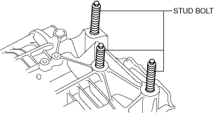
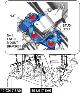
4. Tighten the transaxle stud bolts.
-
Note
-
• When loosening the No.4 engine mount bracket nuts, tighten the transaxle stud bolts because they may loosen.
-
Tightening torque
-
15—25 N·m {1.6—2.5 kgf·m, 12—18 ft·lbf}
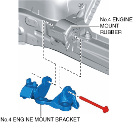
5. Install the No.4 engine mount bracket to the No.4 engine mount rubber and temporarily tighten the No.4 engine mount bracket installation bolt.
6. Lift up the transaxle using the SSTs, pass the stud bolts through the No.4 engine mount bracket, and temporarily tighten the No.4 engine mount bracket installation nuts.
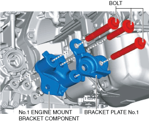
7. Temporarily tighten the No.1 engine mount bracket component and bracket plate No.1 installation bolts.
8. Install the front crossmember component and No.1 engine mount rubber as a single unit. (See FRONT CROSSMEMBER REMOVAL/INSTALLATION.)
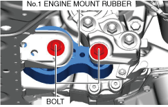
9. Temporarily tighten the No.1 engine mount rubber installation bolts.
10. Align the positions of the No.4 engine mount bracket installation nuts with the No.4 engine mount bracket.
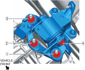
11. Tighten the No.4 engine mount bracket installation bolts and nuts in the order shown in the figure.
|
No.
|
Tightening torque
|
|
1, 2, 3
|
92—116 N·m {9.4—11 kgf·m, 68—85 ft·lbf}
|
|
4
|
81—99 N·m {8.3—10 kgf·m, 60—73 ft·lbf}
|
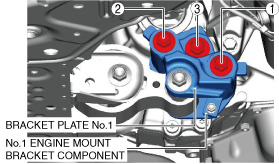
12. Tighten the No.1 engine mount bracket component and bracket plate No.1 installation bolts in the order shown in the figure.
-
Tightening torque
-
131—153 N·m {14—15 kgf·m, 97—112 ft·lbf}
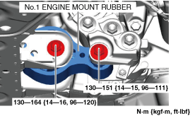
13. Tighten the No.1 engine mount rubber installation bolts.
14. Remove the SSTs (49 C017 5A0, 49 L017 5A0).
15. Secure the crankshaft pulley so that the torque converter does not rotate.
16. Tighten the torque converter installation nuts.
-
Caution
-
• After temporarily tightening the torque converter nuts uniformly, tighten it to the specified torque.
• There are six installation nuts.
-
Tightening torque
-
41—54 N·m {4.2—5.5 kgf·m, 31—39 ft·lbf}
17. Install the blind cover.
18. Install the starter. (See STARTER REMOVAL/INSTALLATION [SKYACTIV-D 2.2].)
19. Install the seal rubber.
20. Connect the front drive shaft (RH) to the transaxle. (See FRONT DRIVE SHAFT REMOVAL/INSTALLATION.)
21. Connect the front drive shaft (LH) to the transaxle. (See FRONT DRIVE SHAFT REMOVAL/INSTALLATION.)
22. Connect the front stabilizer control link to the front stabilizer. (See FRONT STABILIZER INSTALLATION.)
23. Connect the front lower arm to the steering knuckle. (See FRONT LOWER ARM REMOVAL/INSTALLATION.)
24. Connect the tie-rod end to the steering knuckle. (See TIE-ROD END REPLACEMENT.)
25. Connect the brake hose clip to the front shock absorber. (See FRONT BRAKE HOSE REMOVAL/INSTALLATION.)
26. Connect the front ABS wheel-speed sensor to the steering knuckle. (See FRONT ABS WHEEL-SPEED SENSOR REMOVAL/INSTALLATION.)
27. Connect the water hose to the oil cooler. (Automatic transaxle replacement) (See OIL COOLER REMOVAL/INSTALLATION [GW6A-EL, GW6AX-EL].)
28. Connect the oil cooler to the transaxle with the hose connected. (Except for automatic transaxle replacement) (See OIL COOLER REMOVAL/INSTALLATION [GW6A-EL, GW6AX-EL].)
29. Install front under cover No.1. (See FRONT UNDER COVER No.1 REMOVAL/INSTALLATION.)
30. Install front under cover No.2. (See FRONT UNDER COVER No.2 REMOVAL/INSTALLATION.)
31. Install the front tires. (See WHEEL AND TIRE REMOVAL/INSTALLATION.)
32. Install the engine cover adapter.
33. Install the EGR cooler. (See EGR COOLER REMOVAL/INSTALLATION [SKYACTIV-D 2.2].)
34. Install the EGR pipe (EGR valve side). (See EGR PIPE REMOVAL/INSTALLATION [SKYACTIV-D 2.2].)
35. Connect the water pipe component. (See EGR COOLER REMOVAL/INSTALLATION [SKYACTIV-D 2.2].)
36. Install the turbocharger air outlet pipe component. (See INTAKE-AIR SYSTEM REMOVAL/INSTALLATION [SKYACTIV-D 2.2].)
37. Install the air inlet pipe. (See INTAKE-AIR SYSTEM REMOVAL/INSTALLATION [SKYACTIV-D 2.2].)
38. Install the engine cover. (See ENGINE COVER REMOVAL/INSTALLATION [SKYACTIV-D 2.2].)
39. Connect the intermediate shaft to the steering gear and linkage. (See STEERING WHEEL AND COLUMN REMOVAL/INSTALLATION.)
40. Install the joint cover. (See STEERING WHEEL AND COLUMN REMOVAL/INSTALLATION.)
41. Connect the breather hose to the transaxle.
42. Install the selector cable bracket.
43. Connect the selector cable to the transaxle. (See SELECTOR CABLE REMOVAL/INSTALLATION.)
44. Connect the ground to the No.4 engine mount bracket.
45. Install the wiring harness bracket.
46. Tighten the wiring harness bracket installation bolts in the order shown in the figure.
47. Connect the control valve body connector.
-
Caution
-
• Be careful that your hand does not touch the terminal as the connector terminal could be damaged.
• Verify that there is no fluid or foreign matter adhering to the inside of the connector before connecting the connector.
• Insert the connector straight as the connector terminal could be damaged.
• Rotate the connector lever until a click is heard.
48. Install the wiring harness bracket.
49. Connect the electric AT oil pump connector.
50. Install the front splash shield. (See SPLASH SHIELD REMOVAL/INSTALLATION.)
51. Install the battery and battery tray. (See BATTERY REMOVAL/INSTALLATION [SKYACTIV-D 2.2].)
52. Install the following parts as a single unit. (See INTAKE-AIR SYSTEM REMOVAL/INSTALLATION [SKYACTIV-D 2.2].)
-
• Air cleaner cover
• Air cleaner element
• Fresh-air duct
• Air cleaner case
• Air hose
• Resonance chamber
53. Connect the negative battery terminal. (See NEGATIVE BATTERY TERMINAL DISCONNECTION/CONNECTION.)
54. Add engine coolant. (See ENGINE COOLANT REPLACEMENT [SKYACTIV-D 2.2].)
55. Add ATF. (See AUTOMATIC TRANSAXLE FLUID (ATF) REPLACEMENT [GW6A-EL, GW6AX-EL].)
56. Perform the “TCM configuration” (Automatic Transaxle Replacement). (See TCM CONFIGURATION [GW6A-EL, GW6AX-EL].)
57. Perform the initial learning. (Automatic transaxle replacement) (See INITIAL LEARNING [GW6A-EL, GW6AX-EL].)
58. Perform the mechanical system test. (See MECHANICAL SYSTEM TEST [GW6A-EL, GW6AX-EL].)