|
1
|
INSPECT ACTIVE BONNET SENSOR (RIGHT, RIGHT)
• Switch the ignition off.
• Disconnect the negative battery terminal and wait for 1 min or more.
• Remove the front bumper.
• Verify that the active bonnet sennsor (right, right) is correctly installed.
• Is the active bonnet sennsor (right, right) correctly installed?
|
Yes
|
Go to the next step.
|
|
No
|
Correctly install the active bonnet sennsor (right, right).
Then go to Step 7.
|
|
2
|
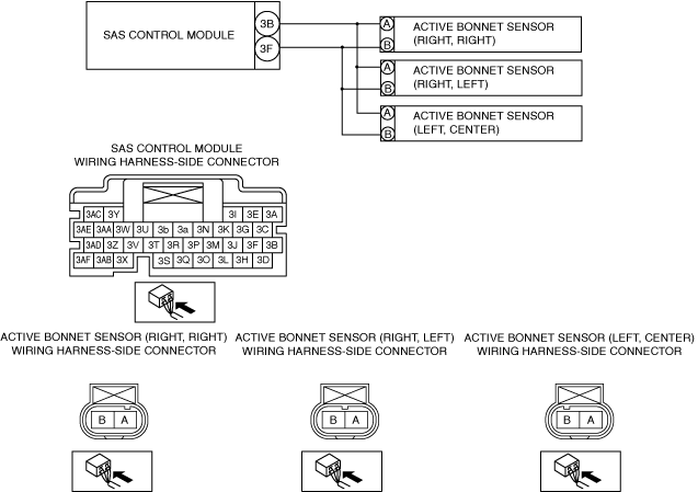
INSPECT ACTIVE BONNET SENNSOR (RIGHT, RIGHT), (RIGHT , LEFT), (LEFT, CENTER) CONNECTOR
• Disconnect the active bonnet sennsor (right, right), (right , left), (left, center) connector.
• Inspect the active bonnet sennsor (right, right), (right , left), (left, center) connector. (Corrosion, damage, and disconnected pins)
• Is there any malfunction of the active bonnet sennsor (right, right), (right , left), (left, center) connector?
|
Yes
|
Replace the malfunctioning part, then go to Step 7.
|
|
No
|
Go to the next step.
|
|
3
|
INSPECT ACTIVE BONNET SENNSOR (RIGHT, RIGHT), (RIGHT , LEFT), (LEFT, CENTER) CIRCUIT FOR SHORT TO GROUND
• Remove the column cover.
• Disconnect the clock spring connector.
• Remove the glove compartment.
• Disconnect the passenger-side air bag module connector.
• Disconnect the driver and passenger-side seat connectors.
• Remove the B-pillar lower trim.
• Remove the trunk side trim.
• Disconnect the driver and passenger-side rear pre-tensioner seat belt connectors.
• Disconnect the driver and passenger-side curtain air bag module connector.
• Disconnect the driver and passenger-side pre-tensioner seat belt connectors.
• Disconnect the active bonnet actuator connectors.
• Disconnect the all SAS control module connectors.
• Inspect for continuity between the following terminals (wiring harness-side) and body ground:
-
― SAS control module terminal 3B
― SAS control module terminal 3F
-
Note
-
• Inspect for continuity while shaking the wiring harness between the SAS control module and active bonnet sennsor (right, right), (right , left), (left, center).
• Is there continuity?
|
Yes
|
Refer to the wiring diagram and verify whether or not there is a common connector between SAS control module terminal and active bonnet sennsor (right, right), (right , left), (left, center) terminal.
If there is a common connector:
• Determine the malfunctioning part by inspecting the common connector and the terminal for corrosion, damage, or pin disconnection, and the common wiring harness for a short to ground.
• Replace the malfunctioning part.
If there is no common connector:
• Replace the wiring harness which has a short to ground.
Go to Step 7.
|
|
No
|
Go to the next step.
|
|
4
|
INSPECT ACTIVE BONNET SENNSOR (RIGHT, RIGHT) CIRCUIT FOR OPEN CIRCUIT
• Active bonnet sennsor (right, right) and SAS control module connectors are disconnected.
• Inspect for continuity between the following terminals (wiring harness-side):
-
― Active bonnet sennsor (right, right) terminal A—SAS control module terminal 3B
― Active bonnet sennsor (right, right) terminal B—SAS control module terminal 3F
-
Note
-
• Inspect for continuity while shaking the wiring harness between the SAS control module and active bonnet sennsor (right, right).
• Is there continuity?
|
Yes
|
Go to the next step.
|
|
No
|
Refer to the wiring diagram and verify whether or not there is a common connector between SAS control module terminal and active bonnet sennsor (right, right) terminal.
If there is a common connector:
• Determine the malfunctioning part by inspecting the common connector and the terminal for corrosion, damage, or pin disconnection, and the common wiring harness for an open circuit.
• Replace the malfunctioning part.
If there is no common connector:
• Replace the wiring harness which has an open circuit.
Go to Step 7.
|
|
5
|
SHORT CIRCUIT TO ACTIVE BONNET SENSOR (RIGHT, RIGHT), (RIGHT, LEFT), (LEFT, CENTER) AND OTHER ACTIVE BONNET SENSOR OR OTHER AIR BAG MODULE CIRCUITS INSPECTION
• Verify that the active bonnet sensor (right, right), (right, left), (left, center), SAS control module and other air bag module connectors are disconnected.
• Refer to the wiring diagram and inspect for continuity between the active bonnet sensor (right, right), (right, left), (left, center) terminals and other air bag module or active bonnet sensor terminals (wiring harness-side).
-
Note
-
• Inspect for continuity while shaking the wiring harness between the SAS control module, active bonnet sensor and other air bag module.
• Is there continuity?
|
Yes
|
Refer to the wiring diagram and verify whether or not there is a common connector between SAS control module terminal and active bonnet sensor (right, right), (right, left), (left, center) terminal.
If there is a common connector:
• Determine the malfunctioning part by inspecting the common connector and the terminal for corrosion, damage, or pin disconnection, and the common wiring harness for a short to other air bag module or active bonnet sensor circuits.
• Replace the malfunctioning part.
If there is no common connector:
• Replace the wiring harness which has a short to other air bag module or active bonnet sensor circuits.
Go to Step 7.
|
|
No
|
Go to the next step.
|
|
6
|
INSPECT ACTIVE BONNET SENNSOR (RIGHT, RIGHT), (RIGHT , LEFT), (LEFT, CENTER) CIRCUIT FOR SHORT TO POWER SUPPLY
• Active bonnet sennsor (right, right), (right , left), (left, center) and SAS control module connectors are disconnected.
• Connect the negative battery terminal.
• Switch the ignition ON (engine off or on).
• Measure the voltage at the following terminals (wiring harness-side):
-
― SAS control module terminal 3B
― SAS control module terminal 3F
-
Note
-
• Measure the voltage while shaking the wiring harness between the SAS control module and active bonnet sennsor (right, right), (right , left), (left, center).
• Is the voltage 0 V?
|
Yes
|
Replace the active bonnet sennsor (right, right), then go to the next step.
|
|
No
|
Refer to the wiring diagram and verify whether or not there is a common connector between SAS control module terminal and active bonnet sennsor (right, right), (right , left), (left, center) terminal.
If there is a common connector:
• Determine the malfunctioning part by inspecting the common connector and the terminal for corrosion, damage, or pin disconnection, and the common wiring harness for a short to power supply.
• Replace the malfunctioning part.
If there is no common connector:
• Replace the wiring harness which has a short to power supply.
Go to the next step.
|
|
7
|
PERFORM SAS CONTROL MODULE DTC INSPECTION
• Switch the ignition off.
• Disconnect the negative battery terminal and wait for 1 min or more.
• Connect the SAS control module connectors.
• Reconnect all disconnected connectors.
• Connect the negative battery terminal.
• Switch the ignition ON (engine off or on).
• Clear the DTC for the SAS control module using the M-MDS.
• Perform the DTC inspection for the SAS control module using the M-MDS.
• Are the same Pending DTCs present?
|
Yes
|
Repeat the inspection from Step 1.
• If the malfunction recurs, replace the SAS control module.
|
|
No
|
DTC troubleshooting completed.
|