PARKING BRAKE REMOVAL/INSTALLATION [R.H.D.]
id0412008002c6
-
Caution
-
• Performing the following procedures without first removing the ABS wheel‐speed sensor may possibly cause an open circuit in the harness if it is pulled by mistake. Before performing the following procedures, remove the ABS wheel‐speed sensor (axle side) and fix it to an appropriate place where the sensor will not be pulled by mistake while servicing the vehicle.
1. Perform the following procedure and remove the parking brake pedal.
- (1) Remove the dashboard under cover (Driver side). (See DASHBOARD UNDER COVER REMOVAL/INSTALLATION.)
2. Perform the following procedure and remove the front parking brake cable.
- (1) Discharge the refrigerant. (See REFRIGERANT CHARGING.)
- (2) Drain the engine coolant. (See ENGINE COOLANT REPLACEMENT [MZI-3.7].)
- (3) Remove the decoration panel (See DECORATION PANEL REMOVAL/INSTALLATION.)
- (4) Remove the front console box mat. (See FRONT CONSOLE BOX MAT REMOVAL/INSTALLATION.)
- (5) Remove the indicator panel. (See INDICATOR PANEL REMOVAL/INSTALLATION.)
- (6) Remove the front console box. (See FRONT CONSOLE BOX REMOVAL/INSTALLATION.)
- (7) Remove the dashboard under cover. (See DASHBOARD UNDER COVER REMOVAL/INSTALLATION.)
- (8) Remove the side wall. (See SIDE WALL REMOVAL/INSTALLATION.)
- (9) Remove the console panel. (See CONSOLE PANEL REMOVAL/INSTALLATION.)
- (10) Remove the console cover. (See CONSOLE COVER REMOVAL/INSTALLATION.)
- (11) Remove the console. (See CONSOLE REMOVAL/INSTALLATION.)
- (12) Remove the front scuff plate inner. (See FRONT SCUFF PLATE REMOVAL/INSTALLATION
- (13) Remove the front side trim (LH). (See FRONT SIDE TRIM REMOVAL/INSTALLATION.)
- (14) Remove the glove compartment. (See GLOVE COMPARTMENT REMOVAL/INSTALLATION.)
- (15) Remove the bonnet release lever. (See BONNET LATCH AND RELEASE LEVER REMOVAL/INSTALLATION.)
- (16) Remove the lower panel. (See LOWER PANEL REMOVAL/INSTALLATION.)
- (17) Remove the lower column cover. (See COLUMN COVER REMOVAL/INSTALLATION.)
- (18) Remove the driver-side air bag module. (See DRIVER-SIDE AIR BAG MODULE REMOVAL/INSTALLATION.)
- (19) Remove the steering wheel. (See STEERING WHEEL AND COLUMN REMOVAL/INSTALLATION.)
- (20) Remove the combination switch. (See COMBINATION SWITCH REMOVAL/INSTALLATION.)
- (21) Remove the center panel. (See CENTER PANEL REMOVAL/INSTALLATION.)
- (22) Remove the meter hood. (See METER HOOD REMOVAL/INSTALLATION.)
- (23) Remove the instrument cluster. (See INSTRUMENT CLUSTER REMOVAL/INSTALLATION.)
- (24) Remove the audio unit. (See AUDIO UNIT REMOVAL/INSTALLATION.)
- (25) Remove the steering shaft. (See STEERING WHEEL AND COLUMN REMOVAL/INSTALLATION.)
- (26) Remove the A-pillar trim. (See A-PILLAR TRIM REMOVAL/INSTALLATION.)
- (27) Remove the side panel. (See SIDE PANEL REMOVAL/INSTALLATION.)
- (28) Disconnect the front door wiring harness connector (Driver side). (See FRONT DOOR MODULE REMOVAL/INSTALLATION.)
- (29) Remove the brake switch from the brake pedal with the brake switch connector connected. (See BRAKE PEDAL REMOVAL/INSTALLATION [R.H.D.].)
- (30) Remove the selector lever component. (See SELECTOR LEVER COMPONENT REMOVAL/INSTALLATION.)
- (31) Remove the windshield wiper arm. (See WINDSHIELD WIPER ARM AND BLADE REMOVAL/INSTALLATION.)
- (32) Remove the cowl grille. (See COWL GRILLE REMOVAL/INSTALLATION.)
- (33) Remove the windshield wiper motor. (See WINDSHIELD WIPER MOTOR REMOVAL/INSTALLATION.)
- (34) Remove the dashboard. (See DASHBOARD REMOVAL/INSTALLATION.)
- (35) Remove the rear heat duct fasteners and slide the rear heat duct rearward. (See REAR HEAT DUCT COMPONENT REMOVAL/INSTALLATION.)
- (36) Remove the front A/C unit. (See FRONT A/C UNIT REMOVAL/INSTALLATION.)
- (37) Remove the front seat. (See FRONT SEAT REMOVAL/INSTALLATION.)
- (38) Remove the dust cover. (See STEERING WHEEL AND COLUMN REMOVAL/INSTALLATION.)
- (39) Turn the floor covering over until the front parking brake cable cover appears.
- (40) Remove the rear heat duct No.1 (LH). (See REAR HEAT DUCT COMPONENT REMOVAL/INSTALLATION.)
3. Perform the following procedure and remove the rear parking brake cable.
- (1) Remove the under guard. (See CHARCOAL CANISTER, CANISTER VENT (CV) SOLENOID VALVE, AIR FILTER COMPONENT REMOVAL/INSTALLATION [MZI-3.7].)
4. Perform the following procedure and remove the parking brake plate, back plate and wheel hub.
- (1) Remove the rear ABS wheel-speed sensor from the trailing link. (See REAR ABS WHEEL-SPEED SENSOR REMOVAL/INSTALLATION.)
- (2) Remove the rear lateral link. (See REAR LATERAL LINK REMOVAL/INSTALLATION.)
- (3) Remove the rear coil spring. (See REAR COIL SPRING REMOVAL/INSTALLATION.)
- (4) Remove the rear lower arm. (See REAR LOWER ARM REMOVAL/INSTALLATION.)
- (5) Remove the trailing link component. (See REAR TRAILING LINK REMOVAL/INSTALLATION.)
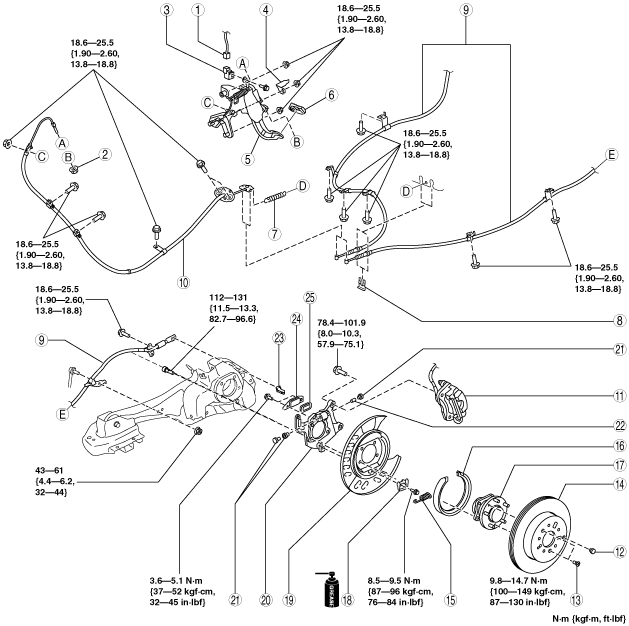
5. Remove in the order indicated in the table.
6. Install in the reverse order of removal.
7. Adjust the parking brake stroke. (See PARKING BRAKE ADJUSTMENT.)
8. Inspect the rear wheel alignment. (See REAR WHEEL ALIGNMENT.)
|
1
|
Parking brake switch connector
|
|
2
|
Adjusting nut
|
|
3
|
Parking brake switch
|
|
4
|
Dashboard under cover bracket
|
|
5
|
Parking brake pedal
|
|
6
|
Parking brake pedal pad
|
|
7
|
Spring
|
|
8
|
Clip
|
|
9
|
Rear parking brake cable
|
|
10
|
Front Parking brake cable, equalizer
|
|
11
|
Brake caliper component
|
|
12
|
Plug
|
|
13
|
Screw
|
|
14
|
Disc plate
|
|
15
|
Spring
|
|
16
|
Parking brake shoe
|
|
17
|
Rear wheel hub component
|
|
18
|
Shoe stopper
|
|
19
|
Backing plate
|
|
20
|
Parking brake plate
|
|
21
|
Adjuster bolt and nut, tappet
|
|
22
|
Pin
|
|
23
|
Operation lever
|
|
24
|
Plate
|
|
25
|
Dust boot
|
Brake Caliper Component Removal Note
1. Remove the brake caliper assembly from the trailing link and suspend it with a cable so it does not interfere.
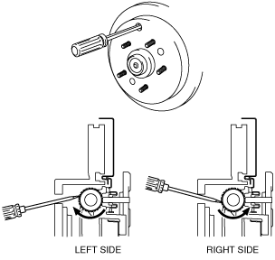
Disc Plate Removal Note
1. If any disc plate is difficult to remove, perform the following steps to remove it.
- (1) Insert a flathead screwdriver into the service hole and turn the adjuster in the direction of the arrow to compress the parking brake shoe.
-
- (2) Remove the disc plate.
Parking Brake Shoe Removal Note
1. Pull the parking brake shoe downward and disengage it from the shoe stopper.
2. Press the adjuster bolt and tappet by hand, and slowly remove the parking brake shoe.
-
Note
-
• When removing the parking brake shoe, firmly press the adjuster bolt and tappet by hand and slowly remove the parking brake shoe to prevent the adjuster bolt, tappet, operation lever and other parts from flying off.
Operation lever, Pin, Adjuster Bolt and Nut, Tappet Installation Note
1. Install the operation lever, pin, adjuster bolt and nut, and tappet so that the adjuster nut is facing toward the vehicle front.
2. Completely tighten the adjuster bolt and nut.
3. Move the operation lever by hand and verify that it operates properly.
-
• If proper operation cannot be verified, reinstall.
Parking Brake Shoe Installation Note
1. Measure the parking brake lining thickness with a vernier caliper or measuring scale.
-
• If it is less than the minimum thickness, install a new parking brake shoe.
-
Minimum parking brake shoe thickness
-
1.0 mm {0.04 in}
2. Apply grease to the contact surface of the parking brake shoe and shoe stopper.
3. After installing the opening of the parking brake shoe to the adjuster bolt and tappet, push the brake shoe upward and attach it to the shoe stopper.
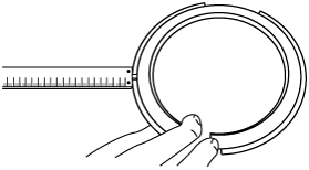
Disc Plate, Screw Installation Note
1. Measure the inner diameter of the disc plate with a vernier caliper.
-
• If it exceeds the maximum diameter, install the new disc plate.
-
Maximum rear disc plate inner diameter
-
191.0 mm {7.52 in}
2. Install the disc plate and screw.
3. Perform the following steps to adjust the shoe clearance after installing the disc plate and the screws.
- (1) Insert a flathead screwdriver into the service hole and turn the adjuster in the direction of the arrow to expand the parking brake shoe until the disc plate cannot rotate.
-
- (2) Return the adjuster 13—25 notches in the direction of the arrow.
-
-
Note
-
• Shoe clearance can be adjusted to 0.15 mm {0.006 in} by returning the adjuster 15 notches.
- (3) Rotate the disc plate and make sure it does not drag.
Front Parking Brake Cable Installation Note
1. Install the front parking brake cable and equalizer so that the installation area of the equalizer spring is on the underside of the vehicle as shown in the vehicle.
Parking Brake Pedal Pad Installation Note
1. Degrease the parking brake pedal pad installation surface of the parking brake pedal.
2. Apply commercially available instant adhesive to the area (shaded area) shown in the figure of the parking brake pedal and install the parking brake pedal pad.
Adjusting Nut Installation Note
1. Verify that the front parking brake cable is installed below the cable deviation prevention tab of the brake cable.
2. Install the adjusting nut.