|
1
|
VERIFY SYSTEM DTCs
• Switch the main power OFF.
• Switch the main power ON (READY off or on) and wait for 10 s or more.
• Perform a Quick Check using the M-MDS.
• Are any DTCs displayed?
|
Yes
|
Repair the malfunctioning location according to the applicable DTC troubleshooting.
|
|
No
|
Go to the next step.
|
|
2
|
VERIFY ELECTRIC PARKING BRAKE WARNING LIGHT ON CONDITION
• Verify if the electric parking brake warning light is turned on.
• Is the electric parking brake warning light turned on?
|
Yes
|
Perform an inspection referring to the [ELECTRIC PARKING BRAKE WARNING LIGHT TURNED ON] item.
|
|
No
|
Go to the next step.
|
|
3
|
DETERMINE MALFUNCTIONING LOCATION BY PERFORMING PID/DATA MONITOR INSPECTION
• Using the M-MDS, display the following PIDs for the door-electrical supply unit (driver’s side).
-
― DOOR_SW_D (front door (driver’s side) open/closed condition)
• Using the M-MDS, display the following PIDs for the dash-electrical supply unit.
-
― S_BELT_STAT (driver’s seat belt fastened condition)
• Does the PID value switch correctly in conjunction with the opening/closing of the front door (driver’s side) or with the driver’s seat belt fastened?
|
Yes
|
Replace the electronically controlled brake unit and perform the repair completion verification.
|
|
No
|
Not in conjunction with front door (driver’s side) open/close:
• Go to the next step.
Not in conjunction with driver's seat belt fastened:
• Go to Step 10.
|
|
4
|
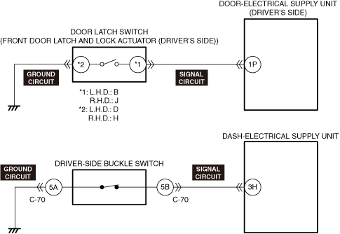
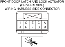
INSPECT FRONT DOOR LATCH AND LOCK ACTUATOR (DRIVER’S SIDE) CONNECTOR FOR MALFUNCTION
• Inspect the applicable connector and terminal.
• Is the connector normal?
|
Yes
|
Go to the next step.
|
|
No
|
Repair or replace the malfunctioning location and perform the repair completion verification.
|
|
5
|
INSPECT FRONT DOOR LATCH SWITCH (DRIVER’S SIDE) FOR MALFUNCTION
• Inspect the applicable part.
• Is the front door latch switch (driver’s side) normal?
|
Yes
|
Go to the next step.
|
|
No
|
Replace the front door latch and lock actuator (driver’s side) and perform the repair completion verification.
|
|
6
|
INSPECT FRONT DOOR LATCH SWITCH (DRIVER’S SIDE) GROUND CIRCUIT FOR OPEN CIRCUIT
• Inspect the applicable circuit for an open circuit.
• Is the circuit normal?
|
Yes
|
Go to the next step.
|
|
No
|
Repair or replace the malfunctioning location and perform the repair completion verification.
|
|
7
|
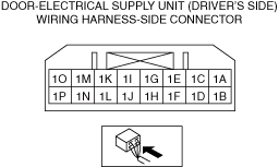
INSPECT DOOR-ELECTRICAL SUPPLY UNIT (DRIVER’S SIDE) CONNECTOR FOR MALFUNCTION
• Inspect the applicable connector and terminal.
• Is the connector normal?
|
Yes
|
Go to the next step.
|
|
No
|
Repair or replace the malfunctioning location and perform the repair completion verification.
|
|
8
|
INSPECT FRONT DOOR LATCH SWITCH (DRIVER’S SIDE) SIGNAL CIRCUIT FOR SHORT TO POWER SUPPLY
• Inspect the applicable circuit for a short to power supply.
• Is the circuit normal?
|
Yes
|
Go to the next step.
|
|
No
|
Repair or replace the malfunctioning location and perform the repair completion verification.
|
|
9
|
INSPECT FRONT DOOR LATCH SWITCH (DRIVER’S SIDE) SIGNAL CIRCUIT FOR OPEN CIRCUIT
• Inspect the applicable circuit for an open circuit.
• Is the circuit normal?
|
Yes
|
Replace the door-electrical supply unit (driver’s side) and perform the repair completion verification.
|
|
No
|
Repair or replace the malfunctioning location and perform the repair completion verification.
|
|
10
|
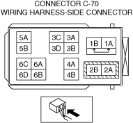
INSPECT CONNECTOR C-70 CONNECTOR FOR MALFUNCTION
• Inspect the applicable connector and terminal.
• Is the connector normal?
|
Yes
|
Go to the next step.
|
|
No
|
Repair or replace the malfunctioning location and perform the repair completion verification.
|
|
11
|
INSPECT DRIVER’S SIDE FRONT BUCKLE SWITCH FOR MALFUNCTION
• Inspect the applicable part.
• Is the driver’s side front buckle switch normal?
|
Yes
|
Go to the next step.
|
|
No
|
Replace the driver’s side front buckle and perform the repair completion verification.
|
|
12
|
INSPECT DRIVER’S SIDE FRONT BUCKLE SWITCH GROUND CIRCUIT FOR OPEN CIRCUIT
• Inspect the applicable circuit for an open circuit.
• Is the circuit normal?
|
Yes
|
Go to the next step.
|
|
No
|
Repair or replace the malfunctioning location and perform the repair completion verification.
|
|
13
|
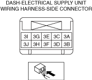
INSPECT DASH-ELECTRICAL SUPPLY UNIT CONNECTOR FOR MALFUNCTION
• Inspect the applicable connector and terminal.
• Is the connector normal?
|
Yes
|
Go to the next step.
|
|
No
|
Repair or replace the malfunctioning location and perform the repair completion verification.
|
|
14
|
INSPECT DRIVER’S SIDE FRONT BUCKLE SWITCH SIGNAL CIRCUIT FOR SHORT TO POWER SUPPLY
• Inspect the applicable circuit for a short to power supply.
• Is the circuit normal?
|
Yes
|
Go to the next step.
|
|
No
|
Repair or replace the malfunctioning location and perform the repair completion verification.
|
|
15
|
INSPECT DRIVER’S SIDE FRONT BUCKLE SWITCH SIGNAL CIRCUIT FOR OPEN CIRCUIT
• Inspect the applicable circuit for an open circuit.
• Is the circuit normal?
|
Yes
|
Replace the dash-electrical supply unit and perform the repair completion verification.
|
|
No
|
Repair or replace the malfunctioning location and perform the repair completion verification.
|
|
Repair completion verification
|
VERIFY IF MALFUNCTION CAUSE IS CORRECTED
• Install/connect the part removed/disconnected during the troubleshooting procedure.
• Has the malfunction symptom been eliminated?
|
Yes
|
Complete the symptom troubleshooting.
Explain repair contents to customer.
|
|
No
|
Refer to the CAN (controller area network) malfunction diagnosis flow to inspect for a CAN communication error.
If the CAN communication is normal, perform the diagnosis from Step 1.
|