 |
a30zzw00001596
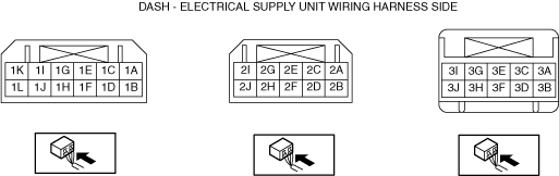
DASH-ELECTRICAL SUPPLY UNIT INSPECTION [FULL-AUTO AIR CONDITIONER]
id0740a1702400
1. Disconnect the negative lead-acid battery terminal and wait for 1 min or more. (See NEGATIVE LEAD-ACID BATTERY TERMINAL DISCONNECTION/CONNECTION.)
2. Remove the following parts:
3. Connect the negative lead-acid battery terminal.
4. Switch the main power ON (READY off or on).
5. Connect the negative (-) lead of the tester to body ground.
6. Insert the positive (+) lead of the tester into each dash-electrical supply unit terminal and measure the voltage according to the terminal voltage table.
Terminal Voltage Table (Reference)
a30zzw00001596
|
|
Terminal |
Signal name |
Connected to |
Measurement condition |
Voltage (V) |
Inspection item (s) |
|
|---|---|---|---|---|---|---|
|
1A
|
Illumi_Foot*1
|
—
|
—
|
—
|
—
|
|
|
1B
|
BL_CONT
|
Blower motor
|
Switch the main power ON (READY off or on)
|
1.0 or less
|
• Related wiring harness
• Blower motor
|
|
|
Switch the main power OFF
|
B+
|
|||||
|
1C
|
—
|
—
|
—
|
—
|
—
|
|
|
1D
|
GND
|
Body ground
|
Under any condition
|
Approx. 0
|
• GND point
• Related wiring harness
|
|
|
1E
|
IG
|
F47 15 A fuse
|
Switch the main power ON (READY off or on)
|
B+
|
• Related wiring harness
• F47 15 A fuse
|
|
|
Switch the main power OFF
|
1.0 or less
|
|||||
|
1F
|
—
|
—
|
—
|
—
|
—
|
|
|
1G
|
BATT
|
F16 15 A fuse
|
Under any condition
|
B+
|
• Related wiring harness
• F16 15 A fuse
|
|
|
1H
|
—
|
—
|
—
|
—
|
—
|
|
|
1I
|
CAN_H_PBLC2
|
CAN related module
|
Because this terminal is for communication, integrity determination by terminal voltage is not possible.
|
• Related wiring harness
|
||
|
1J
|
CAN_L_PBLC2
|
CAN related module
|
Because this terminal is for communication, integrity determination by terminal voltage is not possible.
|
• Related wiring harness
|
||
|
1K
|
CAN_H_PBLC1
|
CAN related module
|
Because this terminal is for communication, integrity determination by terminal voltage is not possible.
|
• Related wiring harness
|
||
|
1L
|
CAN_L_PBLC1
|
CAN related module
|
Because this terminal is for communication, integrity determination by terminal voltage is not possible.
|
• Related wiring harness
|
||
|
2A
|
—
|
—
|
—
|
—
|
—
|
|
|
2B
|
LIN1
|
• Air mix actuator
• Airflow mode actuator
• Air intake actuator
• PTC Heater *3
|
Because this terminal is for communication, integrity determination by terminal voltage is not possible.
|
• Related wiring harness
|
||
|
2C
|
PTC_TEMP_SSR
|
Temperature sensor of air for PTC
|
—
|
Voltage cannot be measured.
|
• Temperature sensor of air for PTC
• Related wiring harness
|
|
|
2D
|
DSCG_TEMP_SSR
|
Temperature sensor of refrigerant line for electric compressor outlet
|
—
|
Voltage cannot be measured.
|
• Temperature sensor of refrigerant line for electric compressor outlet
• Related wiring harness
|
|
|
2E
|
EVA_TEMP_SSR
|
Evaporator temperature sensor
|
—
|
Voltage cannot be measured.
|
• Evaporator temperature sensor
• Related wiring harness
|
|
|
2F
|
—
|
—
|
—
|
—
|
—
|
|
|
2G
|
Sensor GND
|
Evaporator temperature sensor
|
Under any condition
|
1.0 or less
|
• Related wiring harness
|
|
|
2H
|
GND_HVAC_1
|
• Air mix actuator
• Airflow mode actuator
• Air intake actuator
|
Under any condition
|
1.0 or less
|
• Related wiring harness
|
|
|
2I
|
—
|
—
|
—
|
—
|
—
|
|
|
2J
|
IG_HVAC_1
|
• Air mix actuator
• Airflow mode actuator
• Air intake actuator
• PTC heater *3
|
Switch the main power ON (READY off or on)
|
B+
|
• Related wiring harness
|
|
|
Switch the main power OFF
|
B+ / 1.0 or less *5
|
|||||
|
3A
|
CAN_H_PBLC3
|
CAN related module
|
Because this terminal is for communication, integrity determination by terminal voltage is not possible.
|
• Related wiring harness
|
||
|
3B
|
CAN_L_PBLC3
|
CAN related module
|
Because this terminal is for communication, integrity determination by terminal voltage is not possible.
|
• Related wiring harness
|
||
|
3C
|
—
|
—
|
—
|
—
|
—
|
|
|
3D
|
—
|
—
|
—
|
—
|
—
|
|
|
3E
|
—
|
—
|
—
|
—
|
—
|
|
|
3F
|
—
|
—
|
—
|
—
|
—
|
|
|
3G
|
Mode_SW
|
Drive selection switch
|
Switch the main power ON (READY off)
|
Pressed to SPORT side (forward)
|
1.0 or less
|
• Related wiring harness
|
|
Pressed to OFF side (backward)
|
8.0
|
|||||
|
Not pressed
|
9.0
|
|||||
|
3H
|
Buckle switch input
|
Driver-side buckle switch
|
Switch the main power ON (READY off)
|
Driver-side front buckle fastened
|
B+
|
• Related wiring harness
• Driver-side front buckle
|
|
Driver-side front buckle unfastened
|
1.0 or less
|
|||||
|
3I
|
IG_HVAC_2
|
Passenger compartment temperature sensor
|
Switch the main power ON (READY off or on)
|
B+
|
• Related wiring harness
|
|
|
Switch the main power OFF
|
1.0 or less*5
|
|||||
|
3J
|
LIN2
|
Seat warmer control unit *2 / Position memory control module *3 / Heated steering wheel control unit *4
|
Because this terminal is for communication, integrity determination by terminal voltage is not possible.
|
• Related wiring harness
|
||