|
1
|
VERIFY BODY CONTROL MODULE (BCM) DTCs AGAIN
• Clear the DTC recorded in the memory.
• Switch the main power ON (READY off or on) and wait for 10 s or more.
• Perform the DTC inspection for the body control module (BCM).
• Is the same Pending DTC present?
|
Yes
|
Go to the next step.
|
|
No
|
Go to repair completion verification 2.
|
|
2
|
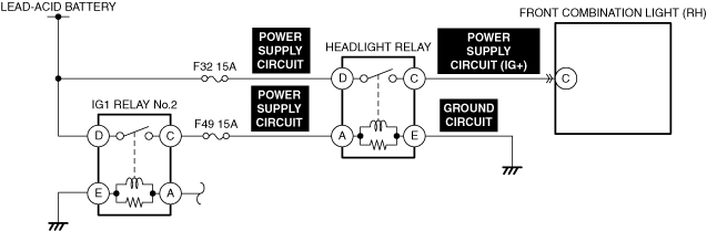
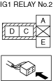
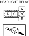
INSPECT IG1 RELAY No.2 AND HEADLIGHT RELAY FOR MALFUNCTION
• Inspect the applicable part.
• Is the part normal?
|
Yes
|
Go to the next step.
|
|
No
|
Repair or replace the malfunctioning location and perform the repair completion verification.
|
|
3
|
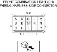
INSPECT FRONT COMBINATION LIGHT (RH) CONNECTOR FOR MALFUNCTION
• Inspect the applicable connector and terminal.
• Are the connector and terminal normal?
|
Yes
|
Go to the next step.
|
|
No
|
Repair or replace the malfunctioning location and perform the repair completion verification.
|
|
4
|
INSPECT FRONT COMBINATION LIGHT (RH) POWER SUPPLY CIRCUIT (IG+) FOR SHORT TO GROUND
• Inspect the applicable circuit for a short to ground.
• Is the circuit normal?
|
Yes
|
Go to the next step.
|
|
No
|
Repair or replace the malfunctioning location and perform the repair completion verification.
|
|
5
|
INSPECT FRONT COMBINATION LIGHT (RH) FOR MALFUNCTION DEPENDING ON REPEATABILITY
• Install/connect the part removed/disconnected during the troubleshooting procedure.
• Clear the DTC recorded in the memory.
• Switch the main power ON (READY off or on) and wait for 10 s or more.
• Perform the DTC inspection for the body control module (BCM).
• Is the same Pending DTC present?
|
Yes
|
Refer to the controller area network (CAN) malfunction diagnosis flow to inspect for a CAN communication error.
If the CAN communication is normal, replace the malfunctioning location and perform the repair completion verification.
|
|
No
|
Go to repair completion verification 2.
|
|
Repair completion verification 1
|
VERIFY THAT VEHICLE IS REPAIRED
• Install/connect the part removed/disconnected during the troubleshooting procedure.
• Clear the DTC recorded in the memory.
• Switch the main power ON (READY off or on) and wait for 10 s or more.
• Perform the DTC inspection for the body control module (BCM).
• Is the same Pending DTC present?
|
Yes
|
Refer to the controller area network (CAN) malfunction diagnosis flow to inspect for a CAN communication error.
If the CAN communication is normal, perform the diagnosis from Step 1.
• If the malfunction recurs, replace the body control module (BCM), then go to the next step.
|
|
No
|
Go to the next step.
|
|
Repair completion verification 2
|
VERIFY IF OTHER DTC IS DISPLAYED
• Perform the DTC inspection.
• Are any other DTCs displayed?
|
Yes
|
Repair the malfunctioning location according to the applicable DTC troubleshooting.
|
|
No
|
DTC troubleshooting completed.
|