|
1
|
VERIFY BODY CONTROL MODULE (BCM) DTCs AGAIN
• Clear the DTC recorded in the memory.
• Switch the main power ON (READY off or on) and wait for 1 s or more.
• Perform the DTC inspection for the body control module (BCM).
• Is the same Pending DTC present?
|
Yes
|
Go to the next step.
|
|
No
|
Go to repair completion verification 2.
|
|
2
|
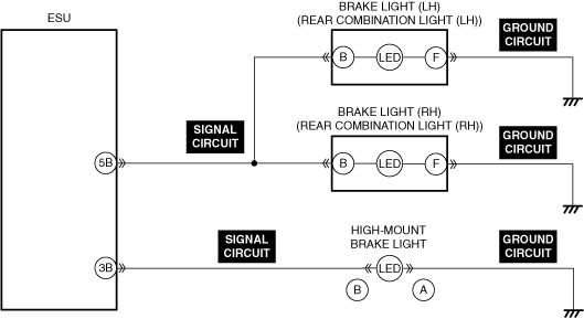
DETERMINE MALFUNCTIONING LIGHT
• Depress the brake pedal.
• Are there any lights among the following which are not turned on?
-
― Brake light (LH)
― Brake light (RH)
― High-mount brake light
|
Yes
|
All lights do not turned on:
• Go to the next step.
Brake light (LH) and brake light (RH) do not turned on:
• Go to Step 4.
High-mount brake light does not turned on:
• Go to Step 11.
|
|
No
|
Go to the next step.
|
|
3
|
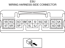
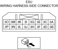
INSPECT ELECTRICAL SUPPLY UNIT (ESU) CONNECTOR FOR MALFUNCTION
• Inspect the applicable connector and terminal.
• Are the connector and terminal normal?
|
Yes
|
Go to the next step.
|
|
No
|
Repair or replace the malfunctioning location and perform the repair completion verification.
|
|
4
|
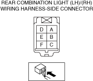
INSPECT REAR COMBINATION LIGHT (LH) CONNECTOR FOR MALFUNCTION
• Inspect the applicable connector and terminal.
• Are the connector and terminal normal?
|
Yes
|
Go to the next step.
|
|
No
|
Repair or replace the malfunctioning location and perform the repair completion verification.
|
|
5
|
INSPECT BRAKE LIGHT (LH) GROUND CIRCUIT FOR OPEN CIRCUIT
• Inspect the applicable circuit for an open circuit.
• Is the circuit normal?
|
Yes
|
Go to the next step.
|
|
No
|
Repair or replace the malfunctioning location and perform the repair completion verification.
|
|
6
|
INSPECT REAR COMBINATION LIGHT (RH) CONNECTOR FOR MALFUNCTION
• Inspect the applicable connector and terminal.
• Are the connector and terminal normal?
|
Yes
|
Go to the next step.
|
|
No
|
Repair or replace the malfunctioning location and perform the repair completion verification.
|
|
7
|
INSPECT BRAKE LIGHT (RH) GROUND CIRCUIT FOR OPEN CIRCUIT
• Inspect the applicable circuit for an open circuit.
• Is the circuit normal?
|
Yes
|
Go to the next step.
|
|
No
|
Repair or replace the malfunctioning location and perform the repair completion verification.
|
|
8
|
INSPECT ELECTRICAL SUPPLY UNIT (ESU) CONNECTOR FOR MALFUNCTION
• Inspect the applicable connector and terminal.
• Are the connector and terminal normal?
|
Yes
|
Go to the next step.
|
|
No
|
Repair or replace the malfunctioning location and perform the repair completion verification.
|
|
9
|
INSPECT BRAKE LIGHT SIGNAL CIRCUIT FOR OPEN CIRCUIT
• Inspect the applicable circuit for an open circuit.
• Is the circuit normal?
|
Yes
|
Go to the next step.
|
|
No
|
Repair or replace the malfunctioning location and perform the repair completion verification.
|
|
10
|
INSPECT BRAKE LIGHT FOR MALFUNCTION
• Install/connect the part removed/disconnected during the troubleshooting procedure.
• Depress the brake pedal.
• Are there any lights among the following which are not turned on?
-
― Brake light (LH)
― Brake light (RH)
|
Yes
|
If the brake light (LH) malfunction does not turn on:
• Replace the brake light (LH) malfunction and perform the repair completion verification.
If the brake light (RH) malfunction does not turn on:
• Replace the brake light (RH) malfunction and perform the repair completion verification.
|
|
No
|
Repair or replace the malfunctioning location and perform the repair completion verification.
|
|
11
|
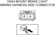
INSPECT HIGH−MOUNT BRAKE LIGHT CONNECTOR FOR MALFUNCTION
• Inspect the applicable connector and terminal.
• Are the connector and terminal normal?
|
Yes
|
Go to the next step.
|
|
No
|
Repair or replace the malfunctioning location and perform the repair completion verification.
|
|
12
|
INSPECT HIGH−MOUNT BRAKE LIGHT GROUND CIRCUIT FOR OPEN CIRCUIT
• Inspect the applicable circuit for an open circuit.
• Is the circuit normal?
|
Yes
|
Go to the next step.
|
|
No
|
Repair or replace the malfunctioning location and perform the repair completion verification.
|
|
13
|
INSPECT ELECTRICAL SUPPLY UNIT (ESU) CONNECTOR FOR MALFUNCTION
• Inspect the applicable connector and terminal.
• Are the connector and terminal normal?
|
Yes
|
Go to the next step.
|
|
No
|
Repair or replace the malfunctioning location and perform the repair completion verification.
|
|
14
|
INSPECT HIGH-MOUNT BRAKE LIGHT SIGNAL CIRCUIT FOR OPEN CIRCUIT
• Inspect the applicable circuit for an open circuit.
• Is the circuit normal?
|
Yes
|
Go to the next step.
|
|
No
|
Repair or replace the malfunctioning location and perform the repair completion verification.
|
|
15
|
INSPECT HIGH-MOUNT BRAKE LIGHT FOR MALFUNCTION
• Inspect the applicable part.
• Is the part normal?
|
Yes
|
Go to the next step.
|
|
No
|
Repair or replace the malfunctioning location and perform the repair completion verification.
|
|
16
|
INSPECT ELECTRICAL SUPPLY UNIT (ESU) FOR MALFUNCTION DEPENDING ON REPEATABILITY
• Install/connect the part removed/disconnected during the troubleshooting procedure.
• Clear the DTC recorded in the memory.
• Switch the main power ON (READY off or on) and wait for 1 s or more.
• Perform the DTC inspection for the body control module (BCM).
• Is the same Pending DTC present?
|
Yes
|
Refer to the controller area network (CAN) malfunction diagnosis flow to inspect for a CAN communication error.
If the CAN communication is normal, replace the malfunctioning location and perform the repair completion verification.
|
|
No
|
Go to the next step.
|
|
Repair completion verification 1
|
VERIFY THAT VEHICLE IS REPAIRED
• Install/connect the part removed/disconnected during the troubleshooting procedure.
• Clear the DTC recorded in the memory.
• Switch the main power ON (READY off or on) and wait for 1 s or more.
• Perform the DTC inspection for the body control module (BCM).
• Is the same Pending DTC present?
|
Yes
|
Refer to the controller area network (CAN) malfunction diagnosis flow to inspect for a CAN communication error.
If the CAN communication is normal, perform the diagnosis from Step 1.
• If the malfunction recurs, replace the body control module (BCM), then go to the next step.
|
|
No
|
Go to the next step.
|
|
Repair completion verification 2
|
VERIFY IF OTHER DTC IS DISPLAYED
• Perform the DTC inspection.
• Are any other DTCs displayed?
|
Yes
|
Repair the malfunctioning location according to the applicable DTC troubleshooting.
|
|
No
|
DTC troubleshooting completed.
|