|
amxzzw00004097
ROOF LINK MOTOR INSPECTION
id091600114500
LH
1. Using the retractable hardtop switch, keep the retractable hardtop half-open.
amxzzw00004097
|
2. Disconnect the negative battery terminal. (See NEGATIVE BATTERY TERMINAL DISCONNECTION/CONNECTION.)
3. Remove the following parts:
4. Remove the seat belt retractor installation bolts and set aside the seat belt retractor. (See SEAT BELT REMOVAL/INSTALLATION.)
5. Remove the lock bracket. (See LOCK BRACKET REMOVAL/INSTALLATION.)
6. Remove the retractable hardtop control module from the seat back crossmember assembly and set it aside so that it does not interfere with the servicing.
7. Remove the seat back crossmember assembly. (See SEAT BACK CROSSMEMBER ASSEMBLY REMOVAL/INSTALLATION.)
8. Remove the roof link assembly. (See ROOF LINK ASSEMBLY REMOVAL/INSTALLATION.)
9. Disconnect the roof link motor connector. (See ROOF LINK MOTOR REMOVAL/INSTALLATION.)
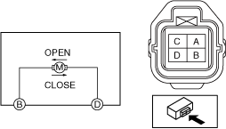
10. Apply battery positive voltage and connect the ground to roof link motor terminals B and D, and then inspect the roof motor operation.
amxzzw00004207
|
|
Operation |
Terminal |
|
|---|---|---|
|
D |
B |
|
|
Open
|
B+
|
Ground
|
|
Close
|
Ground
|
B+
|
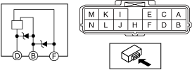
11. Connect the battery positive voltage to top lock limit switch terminal B and connect terminal F to ground.
amxzzw00004208
|
12. Operate the roof motor and measure the voltage at terminal D.
RH
1. Using the retractable hardtop switch, keep the retractable hardtop half-open.
amxzzw00004097
|
2. Disconnect the negative battery terminal. (See NEGATIVE BATTERY TERMINAL DISCONNECTION/CONNECTION.)
3. Remove the following parts:
4. Remove the seat belt retractor installation bolts and set aside the seat belt retractor. (See SEAT BELT REMOVAL/INSTALLATION.)
5. Remove the lock bracket. (See LOCK BRACKET REMOVAL/INSTALLATION.)
6. Remove the retractable hardtop control module from the seat back crossmember assembly and set it aside so that it does not interfere with the servicing.
7. Remove the seat back crossmember assembly. (See SEAT BACK CROSSMEMBER ASSEMBLY REMOVAL/INSTALLATION.)
8. Remove the roof link assembly. (See ROOF LINK ASSEMBLY REMOVAL/INSTALLATION.)
9. Disconnect the roof link motor connector. (See ROOF LINK MOTOR REMOVAL/INSTALLATION.)
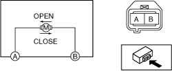
10. Apply battery positive voltage and connect the ground to roof link motor terminals A and B, and then inspect the roof link motor operation.
amxzzw00005686
|
|
Operation |
Terminal |
|
|---|---|---|
|
B |
A |
|
|
Open
|
B+
|
Ground
|
|
Close
|
Ground
|
B+
|
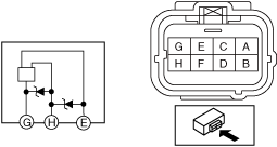
11. Connect the battery positive voltage to roof link limit switch terminal H and connect terminal E to ground.
amxzzw00004210
|
12. Operate the roof link motor and measure the voltage at terminal G.