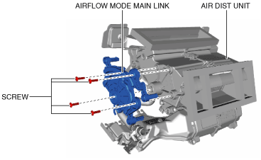
AIRFLOW MODE MAIN LINK REMOVAL/INSTALLATION


id071100801800

Warning
•  Handling the driver-side air bag module improperly can accidentally operate (deploy) the air bag module, which may seriously injure you. Read the SRS air bag system service warnings and cautions before handling the air bag module. (See AIR BAG SYSTEM SERVICE WARNINGS.) (See AIR BAG SYSTEM SERVICE CAUTIONS.)
Caution
•  If a non-specified grease is used, it may result in abnormal noise or an operation malfunction of the links. Use only a grease coating agent on each link and do not wipe off or add additional grease.

1.  Disconnect the negative battery cable and wait for 1 min or more. (See NEGATIVE BATTERY CABLE DISCONNECTION/CONNECTION.)

2.  Remove the following parts:

(1)  Selector lever knob (AT) (See AUTOMATIC TRANSMISSION SHIFT MECHANISM REMOVAL/INSTALLATION.)
(2)  Shift lever knob (MT)
(3)  Shift panel component (See SHIFT PANEL REMOVAL/INSTALLATION.)
(4)  Upper panel (See UPPER PANEL REMOVAL/INSTALLATION.)
(5)  Parking brake lever boot panel (See PARKING BRAKE LEVER BOOT PANEL REMOVAL/INSTALLATION.)
(6)  Rear console (See REAR CONSOLE REMOVAL/INSTALLATION.)
(7)  Front console panel (See FRONT CONSOLE PANEL REMOVAL/INSTALLATION.)
(8)  Front console component (See FRONT CONSOLE REMOVAL/INSTALLATION.)
(9)  Scuff plate (See SCUFF PLATE REMOVAL/INSTALLATION.)
(10)  Front side trim (See FRONT SIDE TRIM REMOVAL/INSTALLATION.)
(11)  A-pillar trim (See A-PILLAR TRIM REMOVAL/INSTALLATION.)
(12)  Passenger-side lower panel (See PASSENGER-SIDE LOWER PANEL REMOVAL/INSTALLATION.)
(13)  Center panel No.2 (See CENTER PANEL No.2 REMOVAL/INSTALLATION.)
(14)  Driver-side air bag module (See DRIVER-SIDE AIR BAG MODULE REMOVAL.) (See DRIVER-SIDE AIR BAG MODULE INSTALLATION.)
(15)  Steering wheel (See STEERING WHEEL AND COLUMN REMOVAL/INSTALLATION.)
(16)  Upper column cover (See COLUMN COVER REMOVAL/INSTALLATION.)
(17)  Lower column cover (See COLUMN COVER REMOVAL/INSTALLATION.)
(18)  Wiper and washer switch (See WIPER AND WASHER SWITCH REMOVAL/INSTALLATION.)
(19)  Light switch (See LIGHT SWITCH REMOVAL/INSTALLATION.)
(20)  Clock spring (See CLOCK SPRING REMOVAL/INSTALLATION.)
(21)  Meter hood (See METER HOOD REMOVAL/INSTALLATION.)
(22)  Instrument cluster (See INSTRUMENT CLUSTER REMOVAL/INSTALLATION.)
(23)  Bonnet release lever (See BONNET RELEASE LEVER AND RELEASE CABLE REMOVAL/INSTALLATION.)
(24)  Driver-side lower panel (See DRIVER-SIDE LOWER PANEL REMOVAL/INSTALLATION.)
(25)  Center panel No.1 (See CENTER PANEL No.1 REMOVAL/INSTALLATION.)
(26)  Climate control unit (See CLIMATE CONTROL UNIT REMOVAL/INSTALLATION [FULL-AUTO AIR CONDITIONER].) (See CLIMATE CONTROL UNIT REMOVAL/INSTALLATION [MANUAL AIR CONDITIONER].)
(27)  Audio unit (without center display) (See AUDIO UNIT REMOVAL/INSTALLATION.)
(28)  Center display (with center display) (See CENTER DISPLAY REMOVAL/INSTALLATION.)
(29)  Dashboard (See DASHBOARD REMOVAL.) (See DASHBOARD INSTALLATION.)
(30)  Air dist unit (See AIR DIST UNIT REMOVAL/INSTALLATION.)
(31)  Airflow mode actuator (See AIRFLOW MODE ACTUATOR REMOVAL/INSTALLATION [FULL-AUTO AIR CONDITIONER].) (See AIRFLOW MODE ACTUATOR REMOVAL/INSTALLATION [MANUAL AIR CONDITIONER].)

3.  Remove the screws.

amxuuw00003891

4.  Remove the airflow mode main link.

5.  Install in the reverse order of removal.