CVT (CONTINUOUSLY VARIABLE TRANSAXLE) REMOVAL/INSTALLATION [DJVA-EL]
id051901287400
-
Note
-
1. Drain the CVT fluid. (See CVT (CONTINUOUSLY VARIABLE TRANSAXLE) FLUID REPLACEMENT [DJVA-EL].)
2. Perform disconnection/removal of the following parts.
- (1) Remove the battery, battery tray, and battery bracket. (See BATTERY REMOVAL/INSTALLATION [MZR 1.3, MZR 1.5].)
-
- (2) Remove the fresh-air duct and the air cleaner as a single unit. (See INTAKE-AIR SYSTEM REMOVAL/INSTALLATION [MZR 1.3, MZR 1.5].)
-
- (3) Disconnect the selector cable from the transaxle.
-
- (4) Disconnect the connector and ground from the transaxle.
-
- (5) Remove the bracket from the transaxle.
-
- (6) Disconnect the oil cooler from the transaxle. (See OIL COOLER REMOVAL/INSTALLATION [DJVA-EL].)
-
- (7) Remove the starter. (See STARTER REMOVAL/INSTALLATION [MZR 1.3, MZR 1.5].)
-
3. Perform disconnection/removal of the following parts:
- (1) Remove the front wheels and tires. (See GENERAL PROCEDURES (SUSPENSION).)
-
- (2) Disconnect the front ABS wheel speed sensor from the steering knuckle. (See FRONT ABS WHEEL-SPEED SENSOR REMOVAL/INSTALLATION.)
-
- (3) Remove the clips and disengage the brake pipe attachments on the left side of the vehicle. (See BRAKE HOSE (FRONT) REMOVAL/INSTALLATION.)
-
- (4) Disconnect the tie-rod end from the steering knuckle. (See FRONT CROSSMEMBER REMOVAL/INSTALLATION.)
-
- (5) Disconnect the front lower arm ball joint from the steering knuckle. (See FRONT LOWER ARM REMOVAL/INSTALLATION.)
-
- (6) Disconnect only the upper side of the stabilizer control link from the shock absorber. (See FRONT SHOCK ABSORBER AND COIL SPRING REMOVAL/INSTALLATION.)
-
- (7) Disconnect the front drive shaft. (See DRIVE SHAFT REMOVAL/INSTALLATION [MZR1.3, MZR 1.5].)
-
- (8) Remove the joint shaft. (See JOINT SHAFT REMOVAL/INSTALLATION [MZR1.3, MZR 1.5].)
-
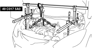
4. Suspend the engine using the SSTs (49 C017 5A0, 49 UN30 3050).
- (1) Remove the brake vacuum hose bracket bolt, then set the brake vacuum hose bracket out of the way.
-
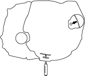
- (2) Set the fuel pipe bracket out of the way to prevent interference with the SST as shown in the figure.
-
- (3) Using the bolts part number 99794 1025 or M10×1.25, length 25 mm {0.98 in} to install the SST to the position shown in the figure.
-
-
Tightening torque
-
38—51 N·m {3.9—5.2 kgf·m, 29—37 ft·lbf}
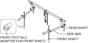
- (4) Install the SST (49 C017 5A0) front foot No.2 to the left and right front shafts.
-
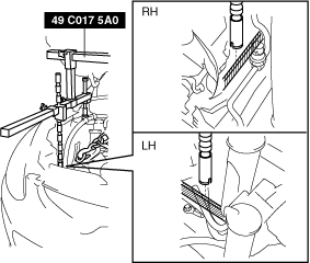
- (5) As shown in the figure, set the rear shafts of the SST to the left and right shock absorber upper bolts.
-
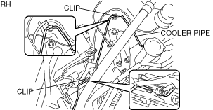
- (6) Remove the cooler pipe from the clips and set it out of the way to prevent interference between the SST and the front shaft.
-
- (7) Remove the front combination light connector from the clips and set it out of the way to prevent interference between the SST and the front shaft.
-
- (8) As shown in the figure, set the front shaft groove of the SST to the folded part of the left and right body frames.
-
- (9) Adjust the height of the left and right side bars so that they are leveled, then tighten each part of the SST.
-
- (10) Verify that the SST is properly set and the engine is securely hung.
-
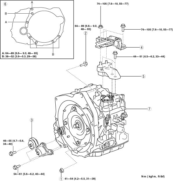
5. Remove the transaxle in the order shown in the figure.
|
1
|
Torque converter installation nuts
|
|
2
|
Transaxle installation bolts (upper side)
|
|
3
|
No.1 Engine mount
|
|
4
|
No.4 Engine mount rubber
|
|
5
|
No.4 Engine mount bracket
|
|
6
|
Transaxle installation bolts (lower side)
|
|
7
|
Transaxle
|
6. Install in the reverse order of removal.
7. Add CVT fluid. (See CVT (CONTINUOUSLY VARIABLE TRANSAXLE) FLUID REPLACEMENT [DJVA-EL].)
8. Perform oil pressure learning. (See TCM LEARNING [DJVA-EL].)
Torque Converter Installation Nuts Removal Note
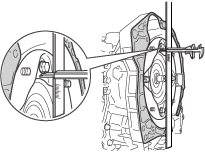
1. Lock the drive plate against rotation using a flathead screwdriver.
2. Remove the torque converter installation nuts from the starter installation hole.
Transaxle Installation Bolts (Lower Side) Removal Note
1. Tilt the engine to the transaxle side using the SST (49 C017 5A0).
2. Support the transaxle using a transmission jack.
3. Remove the transaxle bolts (lower side).
4. Remove the transaxle.
Transaxle Installation Note
-
Caution
-
• Do not drop the torque converter.
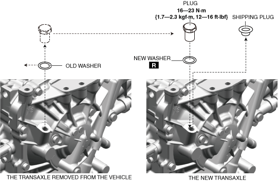
1. If the transaxle is replaced with a new one, perform the following procedure.
- (1) Remove the shipping plug from the new transaxle.
-
- (2) Remove the plug from the transaxle removed from the vehicle.
-
- (3) Perform the CVT fluid adjustment for the new transaxle. (See CVT (CONTINUOUSLY VARIABLE TRANSAXLE) FLUID LEVEL ADJUSTMENT [DJVA-EL].
-
- (4) Install the removed plug and a new washer to the new transaxle.
-
2. Measure the distance from the end of the housing to the bolt installation surface for the torque converter plate to verify that the torque converter is installed correctly.
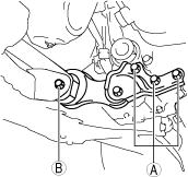
No.4 Engine Mount Rubber Installation Note
1. Install the No.4 engine mount rubber in the order of A and B.
-
Tightening torque
-
74—105 N·m {7.6—10 kgf·m, 55—77 ft·lbf}
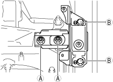
No.1 Engine Mount Installation Note
1. Install the No.1 engine mount in the order of A and B.
-
Tightening torque
-
A:54—61 N·m {5.6—6.2 kgf·m, 40—44 ft·lbf}
B:43—55 N·m {4.4—5.6 kgf·m, 32—40 ft·lbf}