ANTENNA FEEDER NO.1 INSPECTION
id092000812400
1. Disconnect the negative battery cable.
2. Remove the following parts:
- (1) Front scuff plate (See FRONT SCUFF PLATE REMOVAL/INSTALLATION.)
- (2) Front side trim (See FRONT SIDE TRIM REMOVAL/INSTALLATION.)
- (3) Rear console (See REAR CONSOLE REMOVAL/INSTALLATION.)
- (4) Side wall (See SIDE WALL REMOVAL/INSTALLATION.)
- (5) Shift lever knob (MTX) (See MANUAL TRANSAXLE SHIFT MECHANISM REMOVAL/INSTALLATION [F35M-R].) (See MANUAL TRANSAXLE SHIFT MECHANISM REMOVAL/INSTALLATION [B65M-R].)
- (6) Front console component (See FRONT CONSOLE COMPONENT REMOVAL/INSTALLATION.)
- (7) Glove compartment (See GLOVE COMPARTMENT REMOVAL/INSTALLATION.)
- (8) Lower panel (See LOWER PANEL REMOVAL/INSTALLATION.)
- (9) Center panel unit (See CENTER PANEL UNIT REMOVAL/INSTALLATION.)
- (10) A-pillar trim (See A-PILLAR TRIM REMOVAL/INSTALLATION.)
3. Disconnect antenna feeder No.2.
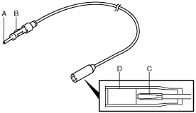
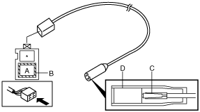
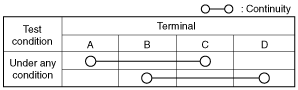
4. Verify that the continuity between antenna feeder No.1 terminals is as indicated in the table.
Without auxiliary jack/USB port
With auxiliary jack/USB port
-
• If not as indicated in the table, replace antenna feeder No.1.