MANUAL TRANSAXLE REMOVAL/INSTALLATION [F66M-R]
id0515n2160000
Special Service Tool (SST)
|
1. : Mazda SST number
2. : Global SST number
|
|
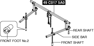
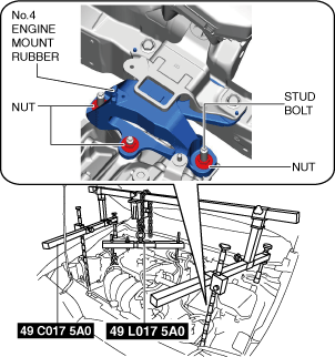
1: 49 C017 5A0
2: –
Engine support set
|
 |
1: 49 UN30 3050
2: 303–050
Engine lifting bracket
|
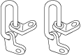 |
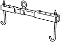
1: 49 L017 5A0
2: –
Support hanger
|
 |
-
Caution
-
• Performing the following procedures could cause an open circuit in the front ABS wheel-speed sensor wiring harness if it is pulled by mistake. Before servicing, disconnect the front ABS wheel-speed sensor and set it aside so that the wiring harness will not be pulled by mistake.
• Secure the steering wheel using tape or a cable to prevent the steering shaft from rotating after disconnecting the steering shaft. If the steering wheel rotates after the steering shaft and the steering gear and linkage are disconnected, the internal parts of the clock spring could be damaged.
Removal
1. Disconnect the negative battery terminal. (See NEGATIVE BATTERY TERMINAL DISCONNECTION/CONNECTION [(E)].)
2. Remove the plug hole plate. (See PLUG HOLE PLATE REMOVAL/INSTALLATION [SKYACTIV-G (WITHOUT CYLINDER DEACTIVATION (E))].)
3. Remove the tunnel cover. (See EXHAUST SYSTEM REMOVAL/INSTALLATION [SKYACTIV-G (WITHOUT CYLINDER DEACTIVATION (E))].)
4. Remove the front under cover No.2. (See FRONT UNDER COVER No.2 REMOVAL/INSTALLATION.)
5. Remove the front under cover No.1. (See FRONT UNDER COVER No.1 REMOVAL/INSTALLATION.)
6. Remove the front deflector. (See DEFLECTOR REMOVAL/INSTALLATION.)
7. Remove the front splash shield. (See SPLASH SHIELD REMOVAL/INSTALLATION.)
8. Drain the manual transaxle oil. (See MANUAL TRANSAXLE OIL REPLACEMENT [F66M-R].)
9. Drain the engine coolant. (See ENGINE COOLANT REPLACEMENT [SKYACTIV-G (WITHOUT CYLINDER DEACTIVATION (E))].)
10. Disconnect the revolution sensor connector and wiring harness clip.
11. Disconnect and/or remove the following parts in the engine compartment.
- (1) Remove the following parts as a single unit. (See INTAKE-AIR SYSTEM REMOVAL/INSTALLATION [SKYACTIV-G (WITHOUT CYLINDER DEACTIVATION (E))].)
-
-
• Air cleaner cover
• Air cleaner element
• Fresh-air duct
• Air cleaner case
• Air hose
• Resonance chamber
- (2) Remove the battery. (See BATTERY REMOVAL/INSTALLATION [SKYACTIV-G (WITHOUT CYLINDER DEACTIVATION (E))].)
-
- (3) Remove the battery tray and PCM component as a single unit. (See BATTERY REMOVAL/INSTALLATION [SKYACTIV-G (WITHOUT CYLINDER DEACTIVATION (E))].)
-
- (4) Disconnect the control cable from manual transaxle. (See CONTROL CABLE REMOVAL/INSTALLATION [F66M-R].)
-
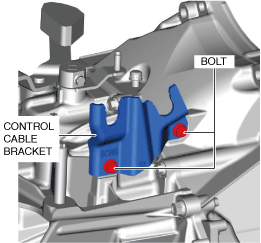
- (5) Remove the control cable bracket from manual transaxle.
-
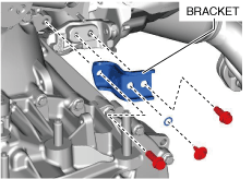
- (6) Remove the bracket from the manual transaxle and the exhaust manifold.
-
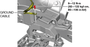
- (7) Remove the bolt shown in the figure, and set the ground cable aside.
-
- (8) Disconnect the neutral sensor No.1 connector from manual transaxle. (See NEUTRAL SENSOR REMOVAL/INSTALLATION [F66M-R].)
-
- (9) Disconnect the neutral sensor No.2 connector from manual transaxle. (with i-stop) (See NEUTRAL SENSOR REMOVAL/INSTALLATION [F66M-R].)
-
- (10) Disconnect the back-up light switch connector from manual transaxle. (See BACK-UP LIGHT SWITCH REMOVAL/INSTALLATION [F66M-R].)
-
- (11) Remove the lower radiator hose component. (See RADIATOR REMOVAL/INSTALLATION [SKYACTIV-G (WITHOUT CYLINDER DEACTIVATION (E))].) (See COOLANT CONTROL VALVE REMOVAL/INSTALLATION [SKYACTIV-G (WITHOUT CYLINDER DEACTIVATION (E))].)
-
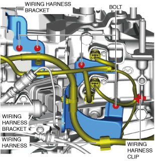
- (12) Remove the wiring harness clip and bolts, and set the wiring harnesses and wiring harness brackets in a place which does not interfere with servicing.
-
12. Remove the joint cover. (See STEERING WHEEL AND COLUMN REMOVAL/INSTALLATION [(E)].)
13. Disconnect the intermediate shaft from the steering gear and linkage. (See STEERING WHEEL AND COLUMN REMOVAL/INSTALLATION [(E)].)
14. Disconnect and/or remove the following parts related to the suspension and axle.
- (1) Remove the front tires. (See WHEEL AND TIRE REMOVAL/INSTALLATION.)
-
- (2) Disconnect the tie-rod ends from the steering knuckles. (See TIE-ROD END REPLACEMENT.)
-
- (3) Disconnect the front lower arm ball joints from the steering knuckle. (See FRONT LOWER ARM REMOVAL/INSTALLATION [(E)].)
-
- (4) Disconnect the front drive shaft (LH) from the manual transaxle. (See FRONT DRIVE SHAFT REMOVAL/INSTALLATION [(E)].)
-
- (5) Disconnect the front drive shaft (RH) from the manual transaxle. (See FRONT DRIVE SHAFT REMOVAL/INSTALLATION [(E)].)
-
15. Disconnect and/or remove the following parts from the underside of the vehicle.
- (1) Remove the clutch release cylinder with the clutch pipe still connected and set it out of the way. (See CLUTCH RELEASE CYLINDER REMOVAL/INSTALLATION [F66M-R].)
-
- (2) Remove the starter. (See STARTER REMOVAL/INSTALLATION [SKYACTIV-G (WITHOUT CYLINDER DEACTIVATION (E))].)
-
- (3) Remove the front crossmember component and No.1 engine mount rubber as a single unit. (See FRONT CROSSMEMBER REMOVAL/INSTALLATION [(E)].)
-
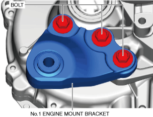
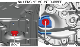
- (4) Remove the No.1 engine mount bracket from the manual transaxle.
-
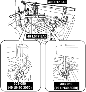
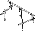
16. Install the SST (49 C017 5A0, 49 UN30 3050, 49 L017 5A0) using the following procedure.
-
Caution
-
• Refer to the SST (49 C017 5A0) instruction manual for the basic handing procedure.
- (1) Install one front foot No.2 to each of the left and right front shafts of the SST (49 C017 5A0).
-
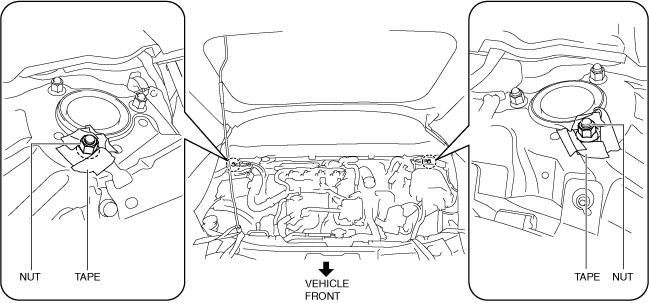
- (2) Protect the positions shown in the figure using tape.
-
- (3) Remove the coolant reserve tank. (See COOLANT RESERVE TANK REMOVAL/INSTALLATION [SKYACTIV-G (WITHOUT CYLINDER DEACTIVATION (E))].)
-
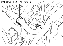
- (4) To enable to install the SST (49 UN30 3050), disconnect the clip shown in the figure and set the wiring harness aside.
-
- (5) Install the SST (49 UN30 3050) to the position shown in the figure using the following bolt.
-
-
Bolt
-
Part number 99794 1025 or an M10 × 1.25, length 25 mm {0.98 in}
- (6) Install the SST (49 UN30 3050) to the position shown in the figure using the following bolt.
-
-
Bolt
-
Part number 99794 1025 or an M10 × 1.25, length 25 mm {0.98 in}
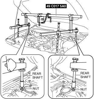
- (7) Set the rear shafts of the SST (49 C017 5A0) on the left/right front shock absorber nuts (top) as shown in the figure.
-
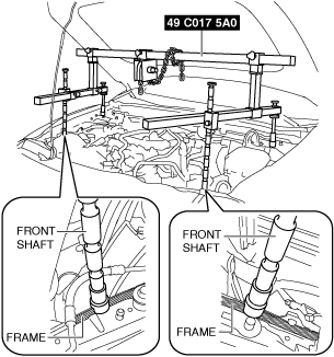
- (8) Set the front shafts of the SST (49 C017 5A0) as shown in the figure.
-
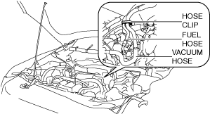
- (9) To prevent interference of the SST with the hose when assembling the SST (49 L017 5A0), disconnect the hose clip from the bracket shown in the figure and set the fuel hose and vacuum hose aside.
-
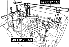
- (10) Install the SST (49 L017 5A0) to the SST (49 C017 5A0) as shown in the figure.
-
- (11) Install the SST (49 L017 5A0) to the SST (49 UN30 3050) with the hook of the SST (49 L017 5A0) facing outward.
-
- (12) Adjust the height of the left and right side bars so that they are leveled, then tighten each part of the SST (49 C017 5A0).
-
- (13) Apply tension to the chain to support the engine and verify that the engine is securely hung.
-
17. Remove in the order indicated in the table.
|
1
|
Transaxle mounting bolt (upper side)
|
|
2
|
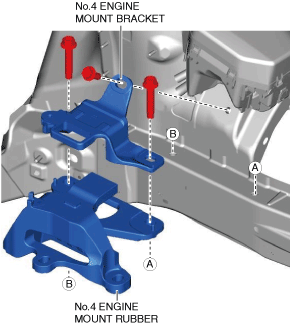
No.4 engine mount bracket
|
|
3
|
No.4 engine mount rubber
|
|
4
|
Transaxle mounting bolt (lower side)
|
|
5
|
Manual transaxle
|
No.4 engine mount rubber and No.4 engine mount bracket removal note
-
Caution
-
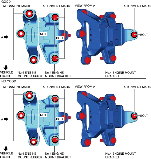
• Slots have been adopted for the No.4 engine mount rubber and No.4 engine mount bracket installation holes. If the No.4 engine mount rubber and No.4 engine mount bracket deviate from their original positions when they are installed, engine noise or vibration could increase. When installing the No.4 engine mount rubber and No.4 engine mount bracket, align them to the alignment marks placed during removal and install them to their original positions.
1. Place alignment marks on the locations shown in the figure so that they can be assembled to the same positions as before removal.
-
Note
-
• Place the alignment marks so that the contour of the nuts and bolts are outlined.
2. Remove the No.4 engine mount rubber and the No.4 engine mount bracket.
Transaxle mounting bolt removal note
-
Warning
-
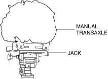
• Remove the manual transaxle carefully, holding it steady. If the manual transaxle falls it could be damaged or cause injury.
1. Adjust the SST (49 C017 5A0) and lean the engine toward the manual transaxle.
2. Support the manual transaxle on a jack.
3. Remove the transaxle mounting bolts (lower side).
4. Remove the manual transaxle.
Installation
-
Warning
-
• Remove the manual transaxle carefully, holding it steady. If the manual transaxle falls it could be damaged or cause injury.
1. Set the manual transaxle on a jack and lift into place.
2. Install the manual transaxle to the engine, and tighten the transaxle mounting bolts.
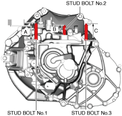
3. Measure the projection of the stud bolts.
-
Projection A of stud bolt No.1
-
70.7—72.7 mm {2.79—2.86 in}
-
Projection B of stud bolt No.2
-
40.0—42.0 mm {1.58—1.65 in}
-
Projection C of stud bolt No.3
-
70.7—72.7 mm {2.79—2.86 in}
-
• If the projection amount is not within the range, adjust the projection amount of the stud bolt.
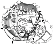
4. Install the No.4 engine mount bracket and the No.4 engine mount rubber, and temporarily tighten the bolts shown in the figure.
5. Lift up the transaxle using the SSTs, pass the stud bolt through the No.4 engine mount rubber, and temporarily tighten the No.4 engine mount rubber installation nuts.
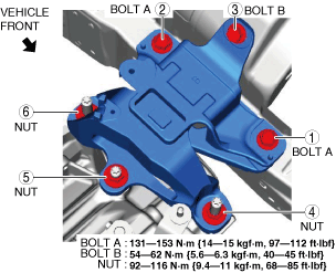
6. Install the No.1 engine mount bracket, and tighten the installation bolts in the order shown in the figure.
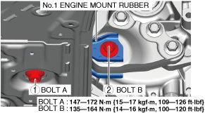
7. Install the front crossmember component and No.1 engine mount rubber as a single unit. (See FRONT CROSSMEMBER REMOVAL/INSTALLATION [(E)].)
8. Temporarily tighten the No.1 engine mount rubber installation bolts.
9. Align the nuts and bolts shown in the figure with the alignment marks.
10. Tighten the No.4 engine mount rubber installation nuts and the No.4 engine mount bracket installation bolts in the order shown in the figure.
11. Remove the SSTs.
12. Tighten the No.1 engine mount rubber installation bolts in the order shown in the figure.
13. Connect and/or install the following parts to the underside of the vehicle.
- (1) Install the starter. (See STARTER REMOVAL/INSTALLATION [SKYACTIV-G (WITHOUT CYLINDER DEACTIVATION (E))].)
-
- (2) Install the clutch release cylinder to the manual transaxle. (See CLUTCH RELEASE CYLINDER REMOVAL/INSTALLATION [F66M-R].)
-
14. Connect and/or install the following parts related to the suspension and axle.
- (1) Install the front drive shaft (RH) to the manual transaxle. (See FRONT DRIVE SHAFT REMOVAL/INSTALLATION [(E)].)
-
- (2) Install the front drive shaft (LH) to the manual transaxle. (See FRONT DRIVE SHAFT REMOVAL/INSTALLATION [(E)].)
-
- (3) Connect the front lower arm ball joint to the steering knuckles. (See FRONT LOWER ARM REMOVAL/INSTALLATION [(E)].)
-
- (4) Connect the tie-rod ends to the steering knuckles. (See TIE-ROD END REPLACEMENT.)
-
- (5) Install the front tires. (See WHEEL AND TIRE REMOVAL/INSTALLATION.)
-
15. Connect the intermediate shaft to the steering gear and linkage. (See STEERING WHEEL AND COLUMN REMOVAL/INSTALLATION [(E)].)
16. Install the joint cover. (See STEERING WHEEL AND COLUMN REMOVAL/INSTALLATION [(E)].)
17. Connect and/or install the following parts in the engine compartment.
- (1) Install the coolant reserve tank. (See COOLANT RESERVE TANK REMOVAL/INSTALLATION [SKYACTIV-G (WITHOUT CYLINDER DEACTIVATION (E))].)
-
- (2) Connect the hose clip to the bracket shown in the figure.
-
- (3) Install the clip shown in the figure.
-
- (4) Install the wiring harness clip and wiring harness bracket.
-
- (5) Install the lower radiator hose component. (See RADIATOR REMOVAL/INSTALLATION [SKYACTIV-G (WITHOUT CYLINDER DEACTIVATION (E))].) (See COOLANT CONTROL VALVE REMOVAL/INSTALLATION [SKYACTIV-G (WITHOUT CYLINDER DEACTIVATION (E))].)
-
- (6) Connect the neutral sensor No.1 connector from manual transaxle. (See NEUTRAL SENSOR REMOVAL/INSTALLATION [F66M-R].)
-
- (7) Connect the neutral sensor No.2 connector from manual transaxle. (with i-stop) (See NEUTRAL SENSOR REMOVAL/INSTALLATION [F66M-R].)
-
- (8) Connect the back-up light switch connector. (See BACK-UP LIGHT SWITCH REMOVAL/INSTALLATION [F66M-R].)
-
- (9) Connect the ground to the No.4 engine mount rubber.
-
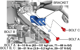
- (10) Install the bracket to the manual transaxle and the exhaust manifold using the following procedure.
-
- 1) Tighten the bolt A.
-
- 2) Temporarily tighten the bolt B and C.
-
- 3) Tighten the bolt B.
-
- 4) Tighten the bolt C.
-
- (11) Install the control cable bracket to the manual transaxle.
-
- (12) Install the control cable to the manual transaxle. (See CONTROL CABLE REMOVAL/INSTALLATION [F66M-R].)
-
- (13) Install the battery tray and PCM component as a single unit. (See BATTERY REMOVAL/INSTALLATION [SKYACTIV-G (WITHOUT CYLINDER DEACTIVATION (E))].)
-
- (14) Install the battery. (See BATTERY REMOVAL/INSTALLATION [SKYACTIV-G (WITHOUT CYLINDER DEACTIVATION (E))].)
-
- (15) Install the following parts as a single unit. (See INTAKE-AIR SYSTEM REMOVAL/INSTALLATION [SKYACTIV-G (WITHOUT CYLINDER DEACTIVATION (E))].)
-
-
• Air cleaner cover
• Air cleaner element
• Fresh-air duct
• Air cleaner case
• Air hose
• Resonance chamber
18. Install the front splash shield. (See SPLASH SHIELD REMOVAL/INSTALLATION.)
19. Install the front deflector. (See DEFLECTOR REMOVAL/INSTALLATION.)
20. Refill the engine coolant. (See ENGINE COOLANT REPLACEMENT [SKYACTIV-G (WITHOUT CYLINDER DEACTIVATION (E))].)
21. Connect the revolution sensor connector and wiring harness clip.
22. Install the tunnel cover. (See EXHAUST SYSTEM REMOVAL/INSTALLATION [SKYACTIV-G (WITHOUT CYLINDER DEACTIVATION (E))].)
23. Install the front under cover No.1. (See FRONT UNDER COVER No.1 REMOVAL/INSTALLATION.)
24. Add the specified amount of manual transaxle oil. (See MANUAL TRANSAXLE OIL REPLACEMENT [F66M-R].)
25. Install the front under cover No.2. (See FRONT UNDER COVER No.2 REMOVAL/INSTALLATION.)
26. Connect the negative battery terminal. (See NEGATIVE BATTERY TERMINAL DISCONNECTION/CONNECTION [(E)].)
27. Install the plug hole plate. (See PLUG HOLE PLATE REMOVAL/INSTALLATION [SKYACTIV-G (WITHOUT CYLINDER DEACTIVATION (E))].)
28. If the manual transaxle is overhauled, perform the “INSPECTION AFTER MANUAL TRANSAXLE OVERHAUL”. (See INSPECTION AFTER MANUAL TRANSAXLE OVERHAUL [F66M-R].)