 |
am3zzw00006872
ENGINE REMOVAL/INSTALLATION [ZY, Z6]
id0110b0800400
1. Remove the battery and battery tray. (See BATTERY REMOVAL/INSTALLATION [ZY, Z6].)
2. Remove the fresh-air duct and the air cleaner component. (See INTAKE-AIR SYSTEM REMOVAL/INSTALLATION [ZY, Z6].)
3. Remove the front wheels and tires. (See GENERAL PROCEDURES (SUSPENSION).)
4. Remove the aerodynamic under cover No.2 and splash shield as a single unit. (See AERODYNAMIC UNDER COVER NO.2 REMOVAL/INSTALLATION.) (See SPLASH SHIELD REMOVAL/INSTALLATION.)
5. Remove the drive belt. (See DRIVE BELT REMOVAL/INSTALLATION [ZY, Z6].)
6. Drain the ATF (ATX), CVT fluid (CVT) or transaxle oil (MTX). (See AUTOMATIC TRANSAXLE FLUID (ATF) REPLACEMENT [FN4A-EL] (ATX).) (See CVT (CONTINUOUSLY VARIABLE TRANSAXLE) FLUID REPLACEMENT [DJVA-EL] (CVT).) (See TRANSAXLE OIL REPLACEMENT [F35M-R] (MTX).)
7. Drain the engine coolant. (See ENGINE COOLANT REPLACEMENT [ZY, Z6].)
8. Remove the coolant reserve tank. (See COOLANT RESERVE TANK REMOVAL/INSTALLATION [ZY, Z6].)
9. Disconnect the vacuum hose from the intake manifold.
10. Disconnect the fuel hose. (See QUICK RELEASE CONNECTOR REMOVAL/INSTALLATION [ZY, Z6].)
11. Disconnect the evaporative hose.
12. Disconnect the radiator hose (upper and lower). (See RADIATOR REMOVAL/INSTALLATION [ZY, Z6].)
13. Disconnect the heater hose.
14. Disconnect the power steering pipe component and then drain the power steering fluid. (See GENERAL PROCEDURES (STEERING).)
15. Disconnect ATF hose, selector cable and wiring harness (ATX). (See AUTOMATIC TRANSAXLE REMOVAL/INSTALLATION [FN4A-EL].)
16. Disconnect the selector cable and wiring harness (CVT). (See CVT (CONTINUOUSLY VARIABLE TRANSAXLE) REMOVAL/INSTALLATION [DJVA-EL].)
17. Disconnect the shift cable and wiring harness (MTX). (See MANUAL TRANSAXLE REMOVAL/INSTALLATION [F35M-R].)
18. Remove the clutch release cylinder with the pipe still connected (MTX). (See CLUTCH RELEASE CYLINDER REMOVAL/INSTALLATION [F35M-R].)
19. Remove the crossmember bracket. (See FRONT CROSSMEMBER REMOVAL/INSTALLATION [ZY, Z6, LF, L3 Turbo, L5, MZ-CD 1.6 (Y6)].)
20. Set the main silencer out of the way. (See EXHAUST SYSTEM REMOVAL/INSTALLATION [ZY, Z6].)
21. Disconnect the drive shafts from the engine side, set the drive shafts out of the way. (See DRIVE SHAFT REMOVAL/INSTALLATION.)
22. Remove the cooling fan component. (See COOLING FAN MOTOR REMOVAL/INSTALLATION [ZY, Z6].)
23. Remove the A/C compressor with the cooler hose still connected and secure it using wire or rope so that it is out of the way. (With A/C) (See A/C COMPRESSOR REMOVAL/INSTALLATION.)
24. Remove the wiring harness installation bolt and nut shown in the figure.
am3zzw00006872
|
25. Disconnect the connectors and the wiring harnesses related to the engine removal/installation.
26. Disconnect the ground cable from the No.3 engine mount.
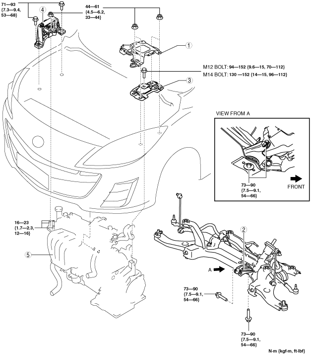
27. Remove in the order indicated in the table.
28. Install in the reverse order of removal.
29. Start the engine and inspect and adjust the following:
am3zzw00008273
|
|
1
|
Battery tray bracket
|
|
2
|
No.1 engine mount rubber, front crossmember component
|
|
3
|
No.4 engine mount rubber
|
|
4
|
No.3 engine mount
|
|
5
|
Engine, transaxle
|
No.1 Engine Mount Rubber, Front Crossmember Component Removal Note
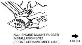
1. Loosen the No.1 engine mount rubber installation bolt (front crossmember side) shown in the figure.
am3zzw00006925
|
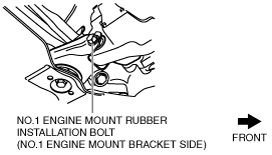
2. Remove the No.1 engine mount rubber installation bolt (No.1 engine mount bracket side) shown in the figure.
am3zzw00006926
|
3. Remove the No.1 engine mount rubber and the front crossmember component as a single unit. (See FRONT CROSSMEMBER REMOVAL/INSTALLATION [ZY, Z6, LF, L3 Turbo, L5, MZ-CD 1.6 (Y6)].)
No.3 Engine Mount, No.4 Engine Mount Rubber Removal Note
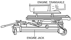
1. Secure the engine and transaxle using an engine jack.
am3zzw00006876
|
Engine Mount Installation Note
1. Tighten the No. 3 engine mount stud bolts.
am3zzw00006877
|
2. Secure the engine and transaxle using an engine jack.
am3zzw00006876
|
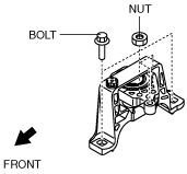
3. Temporarily tighten the No.3 engine mount installation bolts and nuts.
am3zzw00009061
|
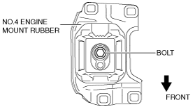
4. Temporarily tighten the No.4 engine mount rubber installation bolt as shown in the figure.
am3zzw00008440
|
5. Install the No.1 engine mount rubber and the front crossmember component as a single unit. (See FRONT CROSSMEMBER REMOVAL/INSTALLATION [ZY, Z6, LF, L3 Turbo, L5, MZ-CD 1.6 (Y6)].)
6. Temporarily tighten the No.1 engine mount rubber installation bolts in the order shown.
am3zzw00006927
|
7. Tighten the No.3 engine mount installation bolts and nuts in the order shown in the figure.
am3zzw00006878
|
|
No. |
Tightening torque |
|---|---|
|
1
|
44—61 N·m {4.5—6.2 kgf·m, 33—44 ft·lbf}
|
|
2
|
71—93 N·m {7.3—9.4 kgf·m, 53—68 ft·lbf}
|
8. Tighten the No.4 engine mount rubber installation bolt.
am3zzw00008440
|
9. Tighten the No.1 engine mount rubber installation bolts in the order shown.
am3zzw00006927
|