 |
am3uuw00002975
ENGINE REMOVAL/INSTALLATION [L3 Turbo]
id0110b3800400
1. Remove the battery cover. (See BATTERY REMOVAL/INSTALLATION [L3 Turbo].)
2. Disconnect the negative battery cable.
3. Remove the charge air cooler cover. (See INTAKE-AIR SYSTEM REMOVAL/INSTALLATION [L3 Turbo].)
4. Remove the PCM cover No.1. (See BATTERY REMOVAL/INSTALLATION [L3 Turbo].)
5. Disconnect the PCM connector. (See PCM REMOVAL/INSTALLATION [L3 Turbo].)
6. Remove the battery tray and PCM component. (See BATTERY REMOVAL/INSTALLATION [L3 Turbo].)
7. Remove the air cleaner component. (See INTAKE-AIR SYSTEM REMOVAL/INSTALLATION [L3 Turbo].)
8. Remove the front wheels and tires. (See GENERAL PROCEDURES (SUSPENSION).)
9. Remove the aerodynamic under cover No.2 and splash shield as a single unit. (See AERODYNAMIC UNDER COVER NO.2 REMOVAL/INSTALLATION.) (See SPLASH SHIELD REMOVAL/INSTALLATION.)
10. Drain the transaxle oil. (See TRANSAXLE OIL REPLACEMENT [A26M-R].)
11. Drain the engine coolant. (See ENGINE COOLANT REPLACEMENT [L3 Turbo].)
12. Remove the coolant reserve tank. (See COOLANT RESERVE TANK REMOVAL/INSTALLATION [L3 Turbo].)
13. Disconnect the upper radiator hose. (See RADIATOR REMOVAL/INSTALLATION [L3 Turbo].)
14. Remove the lower radiator hose and pipe component. (See THERMOSTAT REMOVAL/INSTALLATION [L3 Turbo].) (See RADIATOR REMOVAL/INSTALLATION [L3 Turbo].)
15. Disconnect the heater hose. (See A/C UNIT REMOVAL/INSTALLATION.)
16. Disconnect the fuel hose. (See QUICK RELEASE CONNECTOR REMOVAL/INSTALLATION [L3 Turbo].)
17. Disconnect the evaporative hose. (See PURGE SOLENOID VALVE REMOVAL/INSTALLATION [L3 Turbo].)
18. Disconnect the brake vacuum hose. (See VACUUM HOSE REMOVAL/INSTALLATION [L3 Turbo].)
19. Disconnect the power steering pipe component and then drain the power steering fluid. (See GENERAL PROCEDURES (STEERING).)
20. Disconnect the shift cable. (See MANUAL TRANSAXLE REMOVAL/INSTALLATION [A26M-R (L3 Turbo)].)
21. Remove the clutch release cylinder with the pipe still connected. (See CLUTCH RELEASE CYLINDER REMOVAL/INSTALLATION [A26M-R (L3 Turbo)].)
22. Remove the TWC. (See EXHAUST SYSTEM REMOVAL/INSTALLATION [L3 Turbo].)
23. Disconnect the front drive shafts from the engine side, set the drive shafts out of the way. (See DRIVE SHAFT REMOVAL/INSTALLATION.)
24. Remove the A/C compressor with the cooler hose still connected and secure it using wire or rope so that it is out of the way. (See A/C COMPRESSOR REMOVAL/INSTALLATION.)
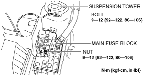
25. Remove the wiring harness installation bolt and nut shown in the figure.
am3uuw00002975
|
26. Disconnect the connectors and the wiring harnesses related to the engine removal/installation.
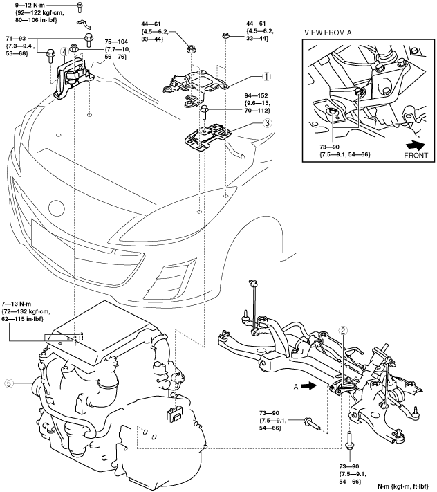
27. Remove in the order indicated in the table.
28. Install in the reverse order of removal.
29. Start the engine, and inspect and adjust the following:
am3zzw00008595
|
|
1
|
Battery tray bracket
|
|
2
|
No.1 engine mount rubber, front crossmember component
|
|
3
|
No.4 engine mount rubber
|
|
4
|
No.3 engine mount
|
|
5
|
Engine, transaxle
|
No.1 Engine Mount Rubber, Front Crossmember Component Removal Note
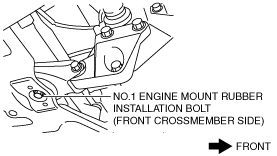
1. Loosen the No.1 engine mount rubber installation bolt (front crossmember side) shown in the figure.
am3uuw00006000
|
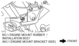
2. Remove the No.1 engine mount rubber installation bolt (No.1 engine mount bracket side) shown in the figure.
am3uuw00006001
|
3. Remove the No.1 engine mount rubber and the front crossmember component as a single unit. (See FRONT CROSSMEMBER REMOVAL/INSTALLATION [ZY, Z6, LF, L3 Turbo, L5, MZ-CD 1.6 (Y6)].)
No.3 Engine Mount, No.4 Engine Mount Rubber Removal Note
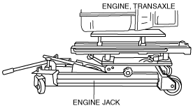
1. Secure the engine and the transaxle using an engine jack.
am6zzw00001215
|
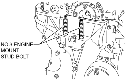
Engine Mount Installation Note
1. Tighten the No. 3 engine mount stud bolts.
am3uuw00006002
|
2. Secure the engine and transaxle using an engine jack.
am6zzw00001215
|
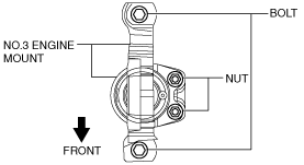
3. Temporarily tighten the No.3 engine mount installation bolts and nuts.
am3zzw00009055
|
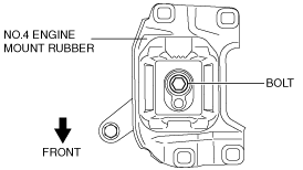
4. Temporarily tighten the No.4 engine mount rubber installation bolt as shown in the figure.
am3uuw00006003
|
5. Install the No.1 engine mount rubber and the front crossmember component as a single unit. (See FRONT CROSSMEMBER REMOVAL/INSTALLATION [ZY, Z6, LF, L3 Turbo, L5, MZ-CD 1.6 (Y6)].)
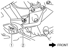
6. Temporarily tighten the No.1 engine mount rubber installation bolts in the order shown in the figure.
am3uuw00006005
|
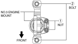
7. Tighten the No.3 engine mount installation bolts and nuts in the order shown in the figure.
am3uuw00003039
|
|
No. |
Tightening torque |
|---|---|
|
1
|
75—104 N·m {7.7—10 kgf·m, 56—76 ft·lbf}
|
|
2
|
71—93 N·m {7.3—9.4 kgf·m, 53—68 ft·lbf}
|
8. Tighten the No.4 engine mount rubber installation bolt.
am3uuw00006003
|
9. Tighten the No.1 engine mount rubber installation bolts in the order shown in the figure.
am3uuw00006005
|