A/C UNIT REMOVAL/INSTALLATION
id071100800200
1. Set the air mix mode to MAX COLD.
2. Disconnect the negative battery cable.
3. Discharge the refrigerant. (See REFRIGERANT CHARGING.)
4. Drain the engine coolant.
5. Remove the engine cover. (L3 Turbo)
6. Remove the insulator. (L3 Turbo)
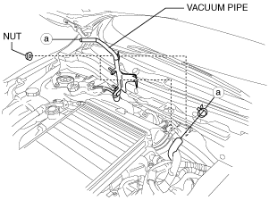
7. Remove the nut and disconnect the vacuum pipe then set the vacuum pipe shown in the figure out of the way. (L3 Turbo) (R.H.D.)
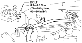
8. Remove the bolt. (L5, Z6, MZ-CD 1.6 (Y6), ZY, L3 Turbo)
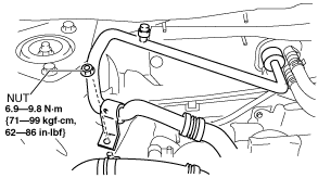
9. Remove the nut. (LF, MZR 2.0 DISI i-stop)
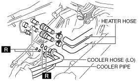
10. Disconnect the following parts from the A/C unit.
-
Caution
-
• If moisture or foreign material enters the refrigeration cycle, cooling ability will be lowered and abnormal noise or other malfunction could occur. Always plug open fittings immediately after removing any refrigeration cycle parts.
- (1) Cooler hose (LO) (See REFRIGERANT LINE REMOVAL/INSTALLATION.)
- (2) Cooler pipe (See REFRIGERANT LINE REMOVAL/INSTALLATION.)
- (3) Heater hose (See Heater Hose Removal Note.) (See Heater Hose Installation Note.)
11. Remove the following parts:
- (1) Front doors (See FRONT DOOR REMOVAL/INSTALLATION.)
- (2) Front scuff plate (See FRONT SCUFF PLATE REMOVAL/INSTALLATION.)
- (3) Front side trim (See FRONT SIDE TRIM REMOVAL/INSTALLATION.)
- (4) Dashboard under cover (See DASHBOARD UNDER COVER REMOVAL/INSTALLATION.)
- (5) Glove compartment (See GLOVE COMPARTMENT REMOVAL/INSTALLATION.)
- (6) Upper panel (See UPPER PANEL REMOVAL/INSTALLATION.)
- (7) Shift lever knob (MTX) (See MANUAL TRANSAXLE SHIFT MECHANISM REMOVAL/INSTALLATION.)
- (8) Selector lever knob (ATX/CVT) (See AUTOMATIC TRANSAXLE SHIFT MECHANISM REMOVAL/INSTALLATION.) (See CVT (CONTINUOUSLY VARIABLE TRANSAXLE) SHIFT MECHANISM REMOVAL/INSTALLATION.)
- (9) Shift panel (See SHIFT PANEL REMOVAL/INSTALLATION.)
- (10) Side wall (See SIDE WALL REMOVAL/INSTALLATION.)
- (11) Console (See CONSOLE REMOVAL/INSTALLATION.)
- (12) Shift lever component (MTX) (See MANUAL TRANSAXLE SHIFT MECHANISM REMOVAL/INSTALLATION.)
- (13) Selector lever component (ATX/CVT) (See AUTOMATIC TRANSAXLE SHIFT MECHANISM REMOVAL/INSTALLATION.) (See CVT (CONTINUOUSLY VARIABLE TRANSAXLE) SHIFT MECHANISM REMOVAL/INSTALLATION.)
- (14) Bonnet release lever (See BONNET LATCH AND RELEASE LEVER REMOVAL/INSTALLATION.)
- (15) Lower panel (See LOWER PANEL REMOVAL/INSTALLATION.)
- (16) Driver-side air bag module (See DRIVER-SIDE AIR BAG MODULE REMOVAL/INSTALLATION.)
- (17) Steering wheel (See STEERING WHEEL AND COLUMN REMOVAL/INSTALLATION [WITHOUT ADVANCED KEYLESS ENTRY AND PUSH BUTTON START SYSTEM].) (See STEERING WHEEL AND COLUMN REMOVAL/INSTALLATION [WITH ADVANCED KEYLESS ENTRY AND PUSH BUTTON START SYSTEM].)
- (18) Column cover (See COLUMN COVER REMOVAL/INSTALLATION.)
- (19) Combination switch (See COMBINATION SWITCH REMOVAL/INSTALLATION.)
- (20) Joint cover (See STEERING WHEEL AND COLUMN REMOVAL/INSTALLATION [WITHOUT ADVANCED KEYLESS ENTRY AND PUSH BUTTON START SYSTEM].) (See STEERING WHEEL AND COLUMN REMOVAL/INSTALLATION [WITH ADVANCED KEYLESS ENTRY AND PUSH BUTTON START SYSTEM].)
- (21) Steering shaft (See STEERING WHEEL AND COLUMN REMOVAL/INSTALLATION [WITHOUT ADVANCED KEYLESS ENTRY AND PUSH BUTTON START SYSTEM].) (See STEERING WHEEL AND COLUMN REMOVAL/INSTALLATION [WITH ADVANCED KEYLESS ENTRY AND PUSH BUTTON START SYSTEM].)
- (22) Center panel (See CENTER PANEL REMOVAL/INSTALLATION.)
- (23) Audio unit (See AUDIO UNIT REMOVAL/INSTALLATION.)
- (24) Climate control unit (See CLIMATE CONTROL UNIT REMOVAL/INSTALLATION [FULL-AUTO AIR CONDITIONER].) (See CLIMATE CONTROL UNIT REMOVAL/INSTALLATION [MANUAL AIR CONDITIONER].)
- (25) Instrument cluster (See INSTRUMENT CLUSTER REMOVAL/INSTALLATION.)
- (26) Center cover (See CENTER COVER REMOVAL/INSTALLATION.)
- (27) Dashboard upper panel (See DASHBOARD UPPER PANEL REMOVAL/INSTALLATION.)
- (28) Hole cover (See HOLE COVER REMOVAL/INSTALLATION.)
- (29) Information display (See INFORMATION DISPLAY REMOVAL/INSTALLATION.)
- (30) A-pillar trim (See A-PILLAR TRIM REMOVAL/INSTALLATION.)
- (31) Windshield wiper arm and blade (See WINDSHIELD WIPER ARM AND BLADE REMOVAL/INSTALLATION.)
- (32) Front fender molding (See COWL GRILLE REMOVAL/INSTALLATION.)
- (33) Cowl grille (See COWL GRILLE REMOVAL/INSTALLATION.)
- (34) Windshield wiper motor (See WINDSHIELD WIPER MOTOR REMOVAL/INSTALLATION.)
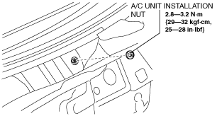
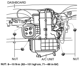
12. Remove the A/C unit installation nut from the engine compartment, then remove the A/C unit.
-
Caution
-
• If moisture or foreign material enters the refrigeration cycle, cooling ability will be lowered and abnormal noise or other malfunction could occur. Always plug open fittings immediately after removing any refrigeration cycle parts.
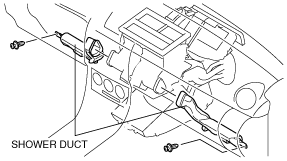
13. Remove the shower ducts.
14. Remove the rear heat duct (1). (See REAR HEAT DUCT REMOVAL/INSTALLATION.)
15. Disconnect the heater core temperature sensor connector. (with i-stop) (See HEATER CORE TEMPERATURE SENSOR REMOVAL/INSTALLATION [FULL-AUTO AIR CONDITIONER].)
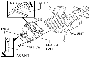
16. Remove the heater case.
-
1. Remove the screws.
2. Pull up tab A in the direction shown by the arrow in the figure and remove it from the A/C unit.
3. Pull up tabs B in the direction shown by the arrow in the figure and remove it from the A/C unit.
17. Disconnect the drain hose connected to the A/C unit. (See Drain Hose Installation Note.)
18. Remove the nuts and bolts for installing the dashboard to the body.
19. Remove the dashboard with A/C unit. (See DASHBOARD REMOVAL/INSTALLATION.)
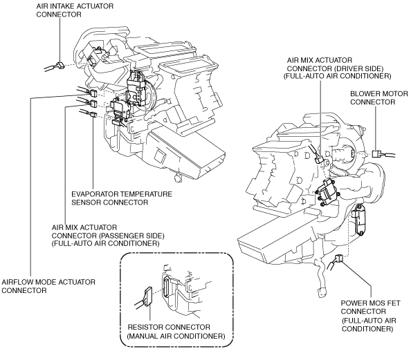
20. Disconnect the following connectors:
-
― Blower motor connector
― Power MOS FET connector (Full-auto air conditioner)
― Resistor connector (Manual air conditioner)
― Evaporator temperature sensor connector
― Air intake actuator connector
― Air mix actuator connector (Full-auto air conditioner)
― Airflow mode actuator connector (Full-auto air conditioner)
L.H.D.
R.H.D.
21. Remove the nuts for installing the A/C unit to the dashboard.
L.H.D.
R.H.D.
22. Install in the reverse order of removal. (See A/C Unit Installation Note.)
23. Inspect for engine coolant leakage. (See ENGINE COOLANT LEAKAGE INSPECTION [LF, L5].) (See ENGINE COOLANT LEAKAGE INSPECTION [L3 Turbo].) (See ENGINE COOLANT LEAKAGE INSPECTION [ZY, Z6].) (See ENGINE COOLANT LEAKAGE INSPECTION [MZR-CD 2.2].)
24. Perform the refrigerant system performance test. (See REFRIGERANT SYSTEM PERFORMANCE TEST.)
A/C Unit Installation Nut Removal Note
-
Note
-
• If the adjusting bolt rotates when removing the A/C unit nut, keep rotating the nut. The adjusting bolt stops rotating when it contacts the A/C unit and the nut can be removed.
A/C Unit Installation Note
1. When replacing the A/C unit or evaporator, add compressor oil to the refrigerant cycle.
-
Supplemental oil amount (approx. quantity)
-
30 ml {30 cc, 1.0 fl oz}
2. Tighten the A/C unit adjusting bolt until it lightly touches the A/C unit.
Drain Hose Installation Note
1. Install the clip as shown in the figure.
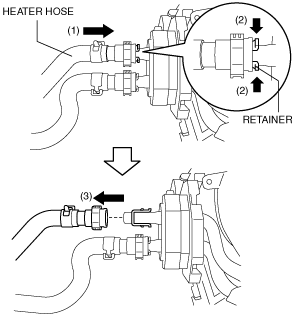
Heater Hose Removal Note
1. While pressing the heater hose into the A/C unit side (1), pinch the quick connector retainer (2), then disconnect the heater hose from the A/C unit (3).
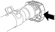
Heater Hose Installation Note
1. Insert the heater hose into the pipe of the A/C unit until a click is heard.
2. While pressing the heater hose quick connector against the A/C unit side, press in the push tab.
3. Verify that the heater hose cannot be pulled out from the A/C unit by lightly pulling the heater hose.