 |
am3zzw00009704
DTC B1317, B1318 [TYPE B]
id0802d5811500
System Malfunction Location
|
DTC |
System Malfunction Location |
|---|---|
|
M-MDS display |
|
|
B1317
|
SAS control module power supply voltage increases (16 V or more)
|
|
B1318
|
SAS control module power supply voltage decreases (8 V or less)
|
Detection Condition
Possible Causes
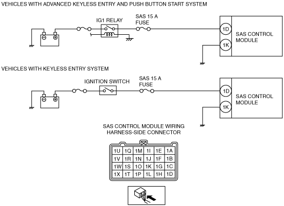
System Wiring Diagram
am3zzw00009704
|
Diagnostic Procedure
|
Step |
Inspection |
Action |
|
|---|---|---|---|
|
1
|
BATTERY INSPECTION
• Refer to the battery inspection and inspect the battery.
(See BATTERY INSPECTION [LF, L5].)
(See BATTERY INSPECTION [ZY, Z6].)
• Is the battery normal?
|
Yes
|
Go to the next step.
|
|
No
|
Replace or charge the battery.
(See BATTERY RECHARGING [LF, L5].)
(See BATTERY RECHARGING [ZY, Z6].)
|
||
|
2
|
FUSE INSPECTION
• Switch the ignition to off.
• Disconnect the negative battery cable and wait 1 min or more.
• Remove the SAS 15 A fuse.
• Is the fuse normal?
|
Yes
|
Go to the next step.
|
|
No
|
Replace the SAS 15 A fuse.
|
||
|
3
|
INSPECT WIRING HARNESS BETWEEN SAS CONTROL MODULE AND IG RELAY/IGNITION SWITCH
• Remove the column cover. (See COLUMN COVER REMOVAL/INSTALLATION.)
• Disconnect the clock spring connector.
• Remove the glove compartment. (See GLOVE COMPARTMENT REMOVAL/INSTALLATION.)
• Disconnect the passenger-side air bag module connector. (See PASSENGER-SIDE AIR BAG MODULE REMOVAL/INSTALLATION.)
• Disconnect the driver and passenger-side front seat connector. (See FRONT SEAT REMOVAL/INSTALLATION.)
• Remove the C-pillar trim. (See C-PILLAR TRIM REMOVAL/INSTALLATION.)
• Disconnect the driver and passenger-side curtain air bag module connector (harness side). (See CURTAIN AIR BAG MODULE REMOVAL/INSTALLATION.)
• Remove the B-pillar lower trim. (See B-PILLAR LOWER TRIM REMOVAL/INSTALLATION.)
• Disconnect the lap pre-tensioner seat belt connector. (See FRONT SEAT BELT REMOVAL/INSTALLATION.)
• Disconnect the driver and passenger-side pre-tensioner seat belt connector. (See FRONT SEAT BELT REMOVAL/INSTALLATION.)
• Remove the console. (See CONSOLE REMOVAL/INSTALLATION.)
• Disconnect all SAS control module connectors. (See SAS CONTROL MODULE REMOVAL/INSTALLATION.)
• Connect the negative battery cable.
• Switch the ignition to ON.
• Measure the voltage of SAS control module connector terminal 1D.
• Is the voltage 8.1–15.9 V?
|
Yes
|
Go to the next step.
|
|
No
|
Replace the wiring harness between the SAS control module and the IG relay/ignition switch.
|
||
|
4
|
INSPECT WIRING HARNESS BETWEEN SAS CONTROL MODULE AND BODY GROUND
• Switch the ignition to off.
• Disconnect the negative battery cable and wait 1 min or more.
• Inspect the wiring harness between SAS control module connector terminal 1K and body ground.
• Is the wiring harness normal?
|
Yes
|
Go to the next step.
|
|
No
|
Replace the wiring harness between the SAS control module and body ground.
|
||
|
5
|
PERFORM SAS CONTROL MODULE DTC INSPECTION
• Reconnect all disconnected connectors.
• Connect the negative battery cable.
• Switch the ignition to ON.
• Clear the DTC for the SAS control module using the M-MDS. (See CLEARING DTC [TYPE B].)
• Perform the DTC inspection for the SAS control module using the M-MDS. (See DTC INSPECTION [TYPE B].)
• Are the same DTCs present?
|
Yes
|
Replace the SAS control module.
|
|
No
|
DTC troubleshooting completed.
|
||