|
am3zzw00010414
POWER BRAKE UNIT REMOVAL/INSTALLATION (R.H.D.) [SKYACTIV-G 2.0]
id0411008038q3
1. Remove the plug hole plate. (See PLUG HOLE PLATE REMOVAL/INSTALLATION [SKYACTIV-G 2.0].)
2. Remove the windshield wiper arm and blade. (See WINDSHIELD WIPER ARM AND BLADE REMOVAL/INSTALLATION.)
3. Remove the cowl grille. (See COWL GRILLE REMOVAL/INSTALLATION.)
4. Remove the cowl panel. (See COWL PANEL REMOVAL/INSTALLATION.)
5. Remove the master cylinder. (See MASTER CYLINDER REMOVAL/INSTALLATION [MZR 2.0 DISI i-stop, SKYACTIV-G 2.0].)
6. Disconnect the vacuum hose connector from the power brake unit. (See VACUUM HOSE REMOVAL/INSTALLATION [SKYACTIV-G 2.0].)
7. Remove the vacuum hose from the vacuum hose clip. (See VACUUM HOSE REMOVAL/INSTALLATION [SKYACTIV-G 2.0].)
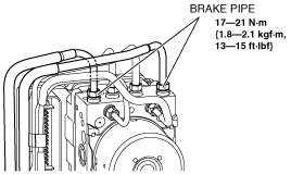
8. Detach the brake pipes from the brake pipe brackets.
am3zzw00010414
|
9. Remove the brake pipes from the DSC HU/CM.
am3zzw00010341
|
10. Remove the coolant reserve tank from the vehicle and move it out of the way.
am3zzw00010415
|
11. Disconnect the steering shaft from the steering gear and linkage. (See STEERING WHEEL AND COLUMN REMOVAL/INSTALLATION [WITHOUT ADVANCED KEYLESS ENTRY AND PUSH BUTTON START SYSTEM].) (See STEERING WHEEL AND COLUMN REMOVAL/INSTALLATION [WITH ADVANCED KEYLESS ENTRY AND PUSH BUTTON START SYSTEM].)
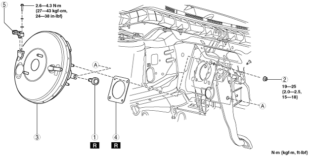
12. Remove in the order indicated in the table.
13. Remove the brake switch. (See BRAKE PEDAL REMOVAL/INSTALLATION [R.H.D.].)
14. Install in the reverse order of removal.
15. After installation, inspect the brake pedal. (See BRAKE PEDAL INSPECTION.)
am3zzw00010342
|
|
1
|
Joint pin
|
|
2
|
Nut
|
|
3
|
Power brake unit
|
|
4
|
Gasket
|
|
5
|
Power brake unit vacuum sensor
|
Power Brake Unit Removal Note
1. Remove the aerodynamic under cover No.2. (See AERODYNAMIC UNDER COVER NO.2 REMOVAL/INSTALLATION.)
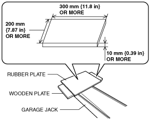
2. Prepare wooden and rubber plates of the sizes shown in the figure and set them to the garage jack.
am3zzw00010343
|
3. Set the tray of the garage jack to the center position of the oil pan bottom surface.
am3zzw00010416
|
4. Remove the No.3 engine mount. (See ENGINE REMOVAL/INSTALLATION [SKYACTIV-G 2.0].)
5. Remove the cooler pipe from the clip.
am3zzw00010417
|
6. Disconnect the refrigerant pressure sensor connector. (See REFRIGERANT PRESSURE SENSOR REMOVAL/INSTALLATION [FULL-AUTO AIR CONDITIONER].)
7. Remove the cooler pipe from the clip.
am3zzw00010418
|
8. Move the cooler pipe in the direction of the arrow.
9. Remove the cooler hose (LO) installation bolt.
am3zzw00010419
|
10. Move the cooler hose (LO) in the direction of the arrow.
11. Operate the garage jack and tilt the engine.
12. Remove the power brake unit while moving the engine towards the vehicle front.