am3zzw00012591
|
ENGINE REMOVAL/INSTALLATION [SKYACTIV-G 2.0]
id0110h2800400
1. Remove the battery cover. (See BATTERY REMOVAL/INSTALLATION [SKYACTIV-G 2.0].)
2. Disconnect the negative battery cable. (See BATTERY REMOVAL/INSTALLATION [SKYACTIV-G 2.0].)
3. Remove the plug hole plate. (See PLUG HOLE PLATE REMOVAL/INSTALLATION [SKYACTIV-G 2.0].)
4. Remove the air cleaner and air hose as a single unit. (See INTAKE-AIR SYSTEM REMOVAL/INSTALLATION [SKYACTIV-G 2.0].)
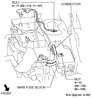
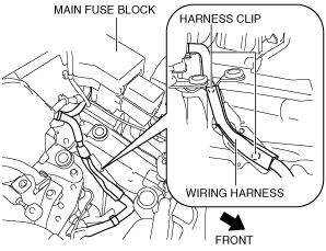
5. Set the wiring harness aside using the following procedure:
am3zzw00012591
|
am3uuw00008797
|
6. Remove the battery tray and PCM component. (See BATTERY REMOVAL/INSTALLATION [SKYACTIV-G 2.0].)
7. Remove the aerodynamic under cover No.2 and splash shield as a single unit. (See AERODYNAMIC UNDER COVER NO.2 REMOVAL/INSTALLATION.) (See SPLASH SHIELD REMOVAL/INSTALLATION.)
8. Drain the engine coolant. (See ENGINE COOLANT REPLACEMENT [SKYACTIV-G 2.0].)
9. Drain the ATF. (See AUTOMATIC TRANSAXLE FLUID (ATF) REPLACEMENT [FW6A-EL].)
10. Remove the front wheels and tires. (See GENERAL PROCEDURES (SUSPENSION).)
11. Disconnect the selector cable. (See AUTOMATIC TRANSAXLE SHIFT MECHANISM REMOVAL/INSTALLATION.)
12. Disconnect the brake vacuum hose. (See VACUUM HOSE REMOVAL/INSTALLATION [SKYACTIV-G 2.0].)
13. Disconnect the evaporative hose. (See PURGE SOLENOID VALVE REMOVAL/INSTALLATION [SKYACTIV-G 2.0].)
14. Disconnect the fuel hose. (See QUICK RELEASE CONNECTOR REMOVAL/INSTALLATION [SKYACTIV-G 2.0].)
15. Disconnect the upper radiator hose. (See RADIATOR REMOVAL/INSTALLATION [SKYACTIV-G 2.0].)
16. Disconnect the heater hose. (See A/C UNIT REMOVAL/INSTALLATION.)
17. Disconnect the lower radiator hose. (See RADIATOR REMOVAL/INSTALLATION [SKYACTIV-G 2.0].)
18. Remove the coolant reserve tank.(See COOLANT RESERVE TANK REMOVAL/INSTALLATION [SKYACTIV-G 2.0].)
19. Remove the generator drive belt. (See DRIVE BELT REMOVAL/INSTALLATION [SKYACTIV-G 2.0].)
20. Remove the A/C compressor with the cooler hose still connected and secure it using wire or rope so that it is out of the way. (See A/C COMPRESSOR REMOVAL/INSTALLATION.)
21. Remove the TWC. (See EXHAUST SYSTEM REMOVAL/INSTALLATION [SKYACTIV-G 2.0].)
22. Disconnect the drive shafts from the engine side, set the drive shafts out of the way. (See DRIVE SHAFT REMOVAL/INSTALLATION.)
23. Disconnect the power steering pipe component and then drain the power steering fluid. (See GENERAL PROCEDURES (STEERING).) (See FRONT CROSSMEMBER REMOVAL/INSTALLATION [MZR 2.0 DISI i-stop, SKYACTIV-G 2.0].)
24. Disconnect the ground cable from the wiring harness bracket.
am3uuw00009040
|
25. Remove in the order indicated in the table.
26. Install in the reverse order of removal.
27. Refill the ATF. (See AUTOMATIC TRANSAXLE FLUID (ATF) REPLACEMENT [FW6A-EL].)
28. Refill the engine coolant. (See ENGINE COOLANT REPLACEMENT [SKYACTIV-G 2.0].)
29. Start the engine, and inspect and adjust the following:
am3zzw00013313
|
|
1
|
Wiring harness bracket
|
|
2
|
Battery tray bracket
|
|
3
|
No.1 engine mount rubber, front crossmember component
|
|
4
|
No.1 engine mount bracket
|
|
5
|
No.4 engine mount rubber
|
|
6
|
No.3 engine mount
|
|
7
|
Engine, transaxle
|
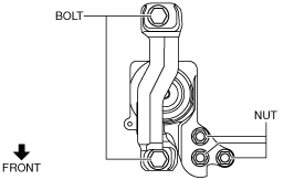
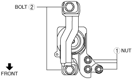
No.1 Engine Mount Rubber, Front Crossmember Component Removal Note
1. Loosen the No.1 engine mount rubber installation bolt A and remove the bolt B.
am3zzw00012593
|
2. Remove the No.1 engine mount rubber and the front crossmember component as a single unit. (See FRONT CROSSMEMBER REMOVAL/INSTALLATION [MZR 2.0 DISI i-stop, SKYACTIV-G 2.0].)
No.3 Engine Mount, No.4 Engine Mount Rubber Removal Note
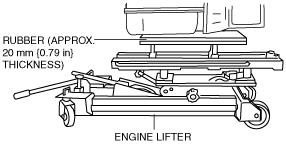
1. Secure the engine and transaxle using a commercially available engine lifter.
am3zzw00013482
|
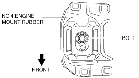
2. Remove the No.4 engine mount rubber.
3. Remove the No.3 engine mount.
Engine Mount Installation Note
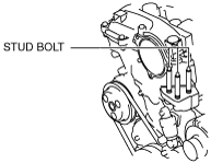
1. Tighten the No.3 engine mount stud bolts.
am3zzw00013483
|
2. Secure the engine and transaxle using a commercially available engine lifter.
am3zzw00013482
|
3. Temporarily tighten the No.3 engine mount installation bolts and nuts.
am3uuw00008804
|
4. Temporarily tighten the No.4 engine mount rubber installation bolt as shown in the figure.
am3uuw00003040
|
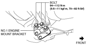
5. Install the No.1 engine mount bracket.
am3zzw00012594
|
6. Install the No.1 engine mount rubber and the front crossmember component as a single unit. (See FRONT CROSSMEMBER REMOVAL/INSTALLATION [MZR 2.0 DISI i-stop, SKYACTIV-G 2.0].)
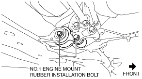
7. Temporarily tighten the No.1 engine mount rubber installation bolts.
am3zzw00012595
|
8. Tighten the No.3 engine mount installation bolts and nuts in the order shown in the figure.
am3zzw00013484
|
|
No. |
Tightening torque |
|---|---|
|
1
|
75—104 N·m {7.7—10 kgf·m, 56—76 ft·lbf}
|
|
2
|
71—93 N·m {7.3—9.4 kgf·m, 53—68 ft·lbf}
|
9. Tighten the No.4 engine mount rubber installation bolt.
am3uuw00003040
|
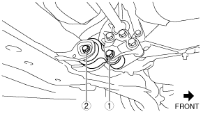
10. Tighten the No.1 engine mount rubber installation bolts in the order shown in the figure.
am3zzw00012596
|
|
No. |
Tightening torque |
|---|---|
|
1
|
71—91 N·m {7.3—9.2 kgf·m, 53—67 ft·lbf}*1
79—102 N·m {8.1—10 kgf·m, 59—75 ft·lbf}*2
|
|
2
|
73—90 N·m {7.5—9.1 kgf·m, 54—66 ft·lbf}
|