 |
am3zzw00007327
CLUTCH UNIT REMOVAL/INSTALLATION [G66M-R]
id0510008003m5
1. Remove the battery cover. (See BATTERY INSPECTION [MZR 2.0, MZR 2.5].)(See BATTERY REMOVAL/INSTALLATION [MZR 2.0 DISI i-stop].)
2. Disconnect the negative battery cable. (See BATTERY INSPECTION [MZR 2.0, MZR 2.5].)(See BATTERY REMOVAL/INSTALLATION [MZR 2.0 DISI i-stop].)
3. Remove the battery component. (ex: battery, battery tray and PCM component) (MZR 2.0, MZR 2.5)(See BATTERY INSPECTION [MZR 2.0, MZR 2.5].)
4. Remove the battery and battery tray. (MZR 2.0 DISI i-stop)(See BATTERY REMOVAL/INSTALLATION [MZR 2.0 DISI i-stop].)
5. Remove the air cleaner component. (See INTAKE-AIR SYSTEM REMOVAL/INSTALLATION [MZR 2.0, MZR 2.5].)(See INTAKE-AIR SYSTEM REMOVAL/INSTALLATION [MZR 2.0 DISI i-stop].)
6. Remove the exhaust manifold insulator installation bolts and set the exhaust manifold insulator aside.
7. Remove the following parts:
8. Drain the transaxle oil into a suitable container. (See TRANSAXLE OIL REPLACEMENT [G66M-R].)
9. Remove the manual transaxle.(See MANUAL TRANSAXLE REMOVAL/INSTALLATION [G66M-R (EXCEPT MZR 2.0 DISI i-stop)].)(See MANUAL TRANSAXLE REMOVAL/INSTALLATION [G66M-R (MZR 2.0 DISI i-stop)].)
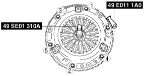
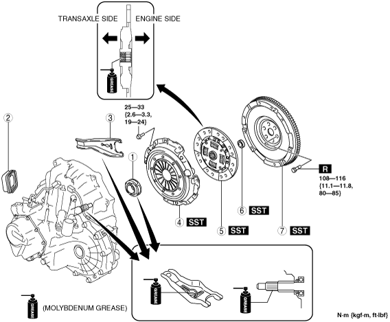
10. Remove in the order indicated in the table.
11. Install in the reverse order of removal.
12. Add the specified amount of specified transaxle oil. (See TRANSAXLE OIL REPLACEMENT [G66M-R].)
am3zzw00007327
|
|
1
|
Clutch release collar
|
|
2
|
Boot
|
|
3
|
Clutch release fork
|
|
4
|
Clutch cover
|
|
5
|
Clutch disc
|
|
6
|
Pilot bearing
(See Pilot Bearing Removal Note.)
|
|
7
|
Flywheel
(See Flywheel Removal Note.)
(See Flywheel Installation Note.)
|
Clutch Release Fork Removal Note
1. Remove the fork supporter before disassembling the clutch release fork.
am3uuw00002080
|
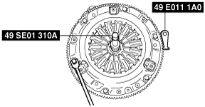
Clutch Cover and Disc Removal Note
1. Install the SSTs.
am3uuw00002081
|
2. Loosen each bolt one turn at a time in a crisscross pattern until spring tension is released.
3. Remove the clutch cover and disc.
Pilot Bearing Removal Note
1. Use the SST to remove the pilot bearing.
am3uuw00002082
|
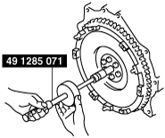
Flywheel Removal Note
1. Hold the flywheel using the SST.
am3uuw00004633
|
2. Remove the bolts evenly and gradually in a crisscross pattern.
3. Remove the flywheel.
am3uuw00002085
|
4. Inspect for oil leakage from the crankshaft rear oil seal.
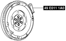
Flywheel Installation Note
1. Install the flywheel to the crankshaft.
2. Clean the crankshaft thread holes before installing the new lock bolts.
3. Hand-tighten the flywheel lock bolts.
4. Install the SST to the flywheel.
am3uuw00002086
|
5. Gradually tighten the flywheel lock bolts in a crisscross pattern.
Pilot Bearing Installation Note
1. Install the pilot bearing using the Snap-on brand millimeter size bushing driver set (A160M) adapter A160M7 (20—22 mm).
am3uuw00002083
|
2. As shown in the figure, press-fit the pilot bearing to the position which is 4.0—5.0 mm {0.16—0.19 in} from the crankshaft end.
am3uuw00002084
|
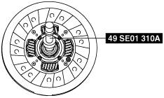
Clutch Disc Installation Note
1. Hold the clutch disc position using the SST.
am3uuw00002087
|
Clutch Cover Installation Note
1. Install the SSTs.
am3uuw00002088
|
2. Tighten the bolts in Min. 2 stages.