 |
am3uuw00002092
CLUTCH COVER INSPECTION [G66M-R]
id0510008008m5
1. Remove the battery cover. (See BATTERY INSPECTION [MZR 2.0, MZR 2.5].)(See BATTERY REMOVAL/INSTALLATION [MZR 2.0 DISI i-stop].)
2. Disconnect the negative battery cable. (See BATTERY INSPECTION [MZR 2.0, MZR 2.5].)(See BATTERY REMOVAL/INSTALLATION [MZR 2.0 DISI i-stop].)
3. Remove the battery component. (ex: battery, battery tray and PCM component) (MZR 2.0, MZR 2.5)(See BATTERY INSPECTION [MZR 2.0, MZR 2.5].)
4. Remove the battery and battery tray. (MZR 2.0 DISI i-stop)(See BATTERY REMOVAL/INSTALLATION [MZR 2.0 DISI i-stop].)
5. Remove the air cleaner component. (See INTAKE-AIR SYSTEM REMOVAL/INSTALLATION [MZR 2.0, MZR 2.5].)(See INTAKE-AIR SYSTEM REMOVAL/INSTALLATION [MZR 2.0 DISI i-stop].)
6. Remove the exhaust manifold insulator installation bolts and set the exhaust manifold insulator aside.
7. Remove the following parts:
8. Drain the transaxle oil into a suitable container. (See TRANSAXLE OIL REPLACEMENT [G66M-R].)
9. Remove the manual transaxle.(See MANUAL TRANSAXLE REMOVAL/INSTALLATION [G66M-R (EXCEPT MZR 2.0 DISI i-stop)].)(See MANUAL TRANSAXLE REMOVAL/INSTALLATION [G66M-R (MZR 2.0 DISI i-stop)].)
10. Remove the clutch cover. (See CLUTCH UNIT REMOVAL/INSTALLATION [G66M-R].)
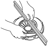
11. Measure the wear of the diaphragm spring fingers.
am3uuw00002092
|
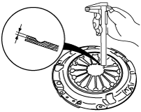
12. Measure the flatness of the pressure plate with a straight edge and a feeler gauge.
am3uuw00002093
|
13. Install the clutch cover. (See CLUTCH UNIT REMOVAL/INSTALLATION [G66M-R].)
14. When checking the diaphragm spring fingers, mount a dial gauge on the cylinder block.
am3uuw00002094
|
15. Rotate the flywheel and check for misaligned diaphragm spring fingers.
16. Install in the reverse order of removal.
17. Add the specified amount of specified transaxle oil. (See TRANSAXLE OIL REPLACEMENT [G66M-R].)