KEY INTERLOCK SYSTEM INSPECTION
id051800297200
Key Interlock System Inspection
1. Switch the ignition to ON.
2. Perform the following procedures to inspect the key interlock system.
-
- (1) Verify that the ignition cannot be switched to off when the selector lever is not in the P position.
- (2) Verify that the ignition can be switched to off when the selector lever is in the P position.
Key Interlock Solenoid Inspection
1. Perform the following procedures.
- (1) Remove the battery cover. (See BATTERY REMOVAL/INSTALLATION [MZR 1.5, MZR 1.6].) (See BATTERY REMOVAL/INSTALLATION [MZR 2.0, MZR 2.5].) (See BATTERY REMOVAL/INSTALLATION [SKYACTIV-G 2.0].)
- (2) Disconnect the negative battery cable. (See BATTERY REMOVAL/INSTALLATION [MZR 1.5, MZR 1.6].) (See BATTERY REMOVAL/INSTALLATION [MZR 2.0, MZR 2.5].) (See BATTERY REMOVAL/INSTALLATION [SKYACTIV-G 2.0].)
- (3) Remove the column cover. (See COLUMN COVER REMOVAL/INSTALLATION.)
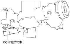
- (4) Disconnect the key interlock solenoid connector.
-
2. Measure the resistance between the key interlock solenoid terminals A and B.
-
-
Key interlock solenoid specification
-
Approx.36 ohms
NOT P Position Switch Inspection
1. Perform the following procedures.
- (1) Remove the battery cover. (See BATTERY REMOVAL/INSTALLATION [MZR 1.5, MZR 1.6].) (See BATTERY REMOVAL/INSTALLATION [MZR 2.0, MZR 2.5].) (See BATTERY REMOVAL/INSTALLATION [SKYACTIV-G 2.0].)
- (2) Disconnect the negative battery cable. (See BATTERY REMOVAL/INSTALLATION [MZR 1.5, MZR 1.6].) (See BATTERY REMOVAL/INSTALLATION [MZR 2.0, MZR 2.5].) (See BATTERY REMOVAL/INSTALLATION [SKYACTIV-G 2.0].)
- (3) Remove the console. (See CONSOLE REMOVAL/INSTALLATION.)
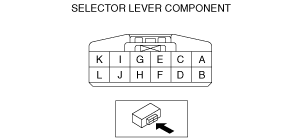
- (4) Disconnect the selector lever component connector.
-
L.H.D.
R.H.D.
2. Inspect the continuity between the selector lever component terminals G and K.
-
NOT P position switch specification
|
Test condition
|
Continuity
|
|
P position
|
No continuity
|
|
Except P position
|
Continuity
|