 |
am3zzw00011062
DTC U2527
id080200000100
System Malfunction Location
Detection Condition
Possible Causes
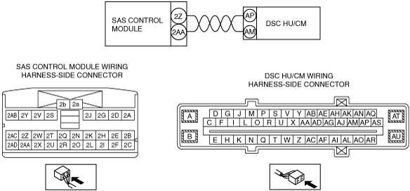
System Wiring Diagram
am3zzw00011062
|
Diagnostic Procedure
|
Step |
Inspection |
Action |
|
|---|---|---|---|
|
1
|
INSPECT DSC HU/CM CONNECTOR
• Switch the ignition to off.
• Disconnect the negative battery cable and wait for 1 min or more.
• Disconnect the DSC HU/CM connector.
• Inspect the DSC HU/CM connector terminals for poor connection (such as damaged/pulled-out pins, and corrosion).
• Is there any malfunction?
|
Yes
|
Repair or replace the terminal, then go to next step.
|
|
No
|
Go to the next step.
|
||
|
2
|
INSPECT SAS CONTROL MODULE CONNECTOR
• Remove the console. (See CONSOLE REMOVAL/INSTALLATION.)
• Disconnect all SAS control module connectors. (See SAS CONTROL MODULE REMOVAL/INSTALLATION.)
• Inspect the SAS control module connector terminal for poor connection (such as damaged/pulled-out pins, and corrosion).
• Is there any malfunction?
|
Yes
|
Repair or replace the terminal, then go to next step.
|
|
No
|
Go to the next step.
|
||
|
3
|
INSPECT WIRING HARNESS BETWEEN DRIVER-SIDE SIDE AIR BAG MODULE AND SAS CONTROL MODULE
• Remove the column cover. (See COLUMN COVER REMOVAL/INSTALLATION.)
• Disconnect the clock spring connector.
• Remove the glove compartment. (See GLOVE COMPARTMENT REMOVAL/INSTALLATION.)
• Disconnect the passenger-side air bag module connector. (See PASSENGER-SIDE AIR BAG MODULE REMOVAL/INSTALLATION.)
• Disconnect the driver and passenger-side front seat connector. (See FRONT SEAT REMOVAL/INSTALLATION.)
• Remove the C-pillar trim. (See C-PILLAR TRIM REMOVAL/INSTALLATION.)
• Disconnect the driver and passenger-side curtain air bag module connector (harness side). (See CURTAIN AIR BAG MODULE REMOVAL/INSTALLATION.)
• Remove the B-pillar lower trim. (See B-PILLAR LOWER TRIM REMOVAL/INSTALLATION.)
• Disconnect the lap pre-tensioner seat belt connector. (See FRONT SEAT BELT REMOVAL/INSTALLATION.)
• Disconnect the driver and passenger-side pre-tensioner seat belt connector. (See FRONT SEAT BELT REMOVAL/INSTALLATION.)
• Inspect the wiring harness between SAS control module terminal 2Z and DSC HU/CM terminal AP, SAS control module terminal 2AA and DSC HU/CM terminal AM for the following:
• Is the wiring harness normal?
|
Yes
|
Go to the next step.
|
|
No
|
Replace the wiring harness between the SAS control module and the DSC HU/CM, then go to next step.
|
||
|
4
|
INSPECT THE WIRING HARNESS BETWEEN THE SAS CONTROL MODULE AND DSC HU/CM FOR A SHORT CIRCUIT TO THE POWER SUPPLY
• Connect the negative battery cable.
• Switch the ignition to ON with SAS control module and DSC HU/CM connector disconnected.
• Measure the voltage of SAS control module connector terminals 2Z and 2AA of SAS control module harness side connector.
• Is the voltage measured?
|
Yes
|
Repair or replace the wiring harness for a possible short to power supply, then go to the next step.
|
|
No
|
Replace the DSC HU/CM, then go to the next step.
|
||
|
5
|
PERFORM SAS CONTROL MODULE DTC INSPECTION
• Switch the ignition to off.
• Disconnect the negative battery cable and wait for 1 min or more.
• Disconnect the SST (Fuel and thermometer checker) or the 2 ohms resistance.
• Connect the driver-side air bag module connector.
• Connect the negative battery cable.
• Switch the ignition to ON.
• Clear the DTC for the SAS control module using the M-MDS. (See CLEARING DTC.)
• Perform the DTC inspection for the SAS control module using the M-MDS. (See DTC INSPECTION.)
• Are the same DTCs present?
|
Yes
|
Replace the SAS control module.
|
|
No
|
DTC troubleshooting completed.
|
||