 |
am3zzw00010498
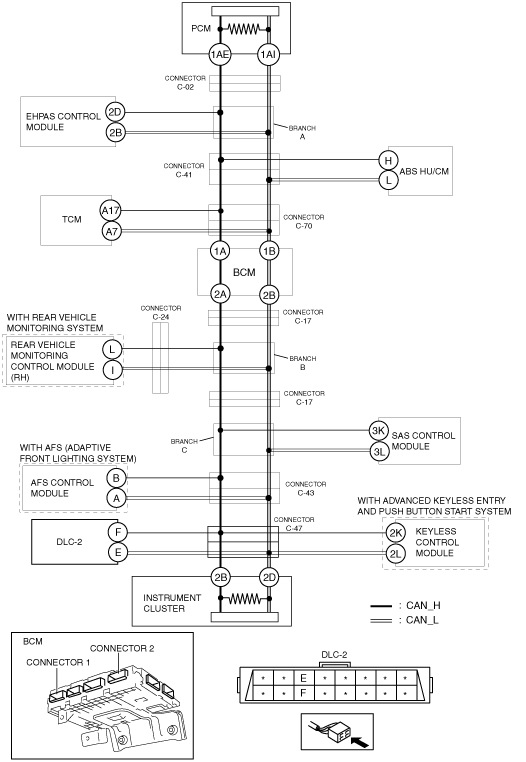
DETERMINING SHORT BETWEEN CIRCUITS LOCATION (HS-CAN) [MULTIPLEX COMMUNICATION SYSTEM (R.H.D. (MZR 1.5))]
id0902m9003900
System wiring diagram
am3zzw00010498
|
Determination procedure
|
Step |
Inspection |
Action |
|
|---|---|---|---|
|
1
|
INSPECT CAN LINE BETWEEN BCM AND INSTRUMENT CLUSTER FOR SHORT BETWEEN CIRCUIT
• Disconnect the negative battery cable.
• Disconnect the BCM connector 1.
• Connect the negative battery cable.
• Switch the ignition ON.
• Measure the voltage at DLC-2 terminals E and F.
• Is the voltage at DLC-2 terminals E and F the same?
|
Yes
|
Go to the next step.
|
|
No
|
Go to Step 16.
|
||
|
2
|
INSPECT CAN LINE IN BCM FOR SHORT BETWEEN CIRCUITS
• Switch the ignition off.
• Disconnect the negative battery cable.
• Disconnect the BCM connector 2.
• Connect the negative battery cable.
• Switch the ignition ON.
• Measure the voltage at DLC-2 terminals E and F.
• Is the voltage at DLC-2 terminals E and F the same?
|
Yes
|
Go to the next step.
|
|
No
|
Replace the BCM because there is a short between circuits in the BCM.
|
||
|
3
|
INSPECT CAN LINE BETWEEN CONNECTOR C-17 AND INSTRUMENT CLUSTER FOR SHORT BETWEEN CIRCUIT
• Switch the ignition off.
• Disconnect the negative battery cable.
• Disconnect connector C-17.
• Connect the negative battery cable.
• Switch the ignition ON.
• Measure the voltage at DLC-2 terminals E and F.
• Is the voltage at DLC-2 terminals E and F the same?
|
Yes
|
Go to Step 7.
|
|
No
|
Go to the next step.
|
||
|
4
|
INSPECT CAN LINE BETWEEN REAR VEHICLE MONITORING CONTROL MODULE (RH) AND CONNECTOR C-17 FOR SHORT BETWEEN CIRCUITS
• Switch the ignition ON.
• Measure the voltage at rear vehicle monitoring control module (RH) terminals L and I.
• Is the voltage at rear vehicle monitoring control module (RH) terminals L and I the same?
|
Yes
|
Go to the next step.
|
|
No
|
Repair or replace the wiring harness between the BCM and connector C-17 because the wiring harness is shorted between circuits.
|
||
|
5
|
INSPECT CAN LINE BETWEEN CONNECTOR C-24 AND REAR VEHICLE MONITORING CONTROL MODULE (RH) FOR SHORT BETWEEN CIRCUIT
• Switch the ignition off.
• Disconnect the negative battery cable.
• Disconnect connector C-24.
• Connect the negative battery cable.
• Switch the ignition ON.
• Measure the voltage at rear vehicle monitoring control module (RH) terminals L and I.
• Is the voltage at rear vehicle monitoring control module (RH) terminals L and I the same?
|
Yes
|
Go to the next step.
|
|
No
|
Repair or replace the wiring harness between connector C-24 and connector C-17 because the wiring harness is shorted between circuits.
|
||
|
6
|
INSPECT CAN LINE IN REAR VEHICLE MONITORING CONTROL MODULE (RH) FOR SHORT BETWEEN CIRCUITS
• Switch the ignition off.
• Disconnect the negative battery cable.
• Connect connector C-24 and connector C-17.
• Disconnect the rear vehicle monitoring control module (RH) connector.
• Connect the negative battery cable.
• Switch the ignition ON.
• Measure the voltage at DLC-2 terminals E and F.
• Is the voltage at DLC-2 terminals E and F the same?
|
Yes
|
Repair or replace the wiring harness between the rear vehicle monitoring control module (RH) and connector C-24 because the wiring harness is shorted between circuits.
|
|
No
|
Replace the rear vehicle monitoring control module (RH) because there is a short between circuits in the rear vehicle monitoring control module (RH).
|
||
|
7
|
INSPECT CAN LINE BETWEEN CONNECTOR C-43 AND INSTRUMENT CLUSTER FOR SHORT BETWEEN CIRCUIT
• Switch the ignition off.
• Disconnect the negative battery cable.
• Disconnect connector C-43.
• Connect the negative battery cable.
• Switch the ignition ON.
• Measure the voltage at DLC-2 terminals E and F.
• Is the voltage at DLC-2 terminals E and F the same?
|
Yes
|
Go to Step 11.
|
|
No
|
Go to the next step.
|
||
|
8
|
INSPECT CAN LINE BETWEEN CONNECTOR C-43 AND AFS CONTROL MODULE FOR SHORT BETWEEN CIRCUITS
• Switch the ignition ON.
• Measure the voltage at AFS control module connector terminals B and A.
• Is the voltage at AFS control module connector terminals B and A the same?
|
Yes
|
Go to the next step.
|
|
No
|
Go to Step 10
|
||
|
9
|
INSPECT CAN LINE IN AFS CONTROL MODULE FOR SHORT BETWEEN CIRCUITS
• Switch the ignition off.
• Disconnect the negative battery cable.
• Connect connector C-43.
• Disconnect the AFS control module connector.
• Connect the negative battery cable.
• Switch the ignition ON.
• Measure the voltage at DLC-2 terminals E and F.
• Is the voltage at DLC-2 terminals E and F the same?
|
Yes
|
Repair or replace the wiring harness between the AFS control module and connector C-43 because the wiring harness is shorted between circuits.
|
|
No
|
Replace the AFS control module because there is a short between circuits in the AFS control module.
|
||
|
10
|
INSPECT CAN LINE IN SAS CONTROL MODULE FOR SHORT BETWEEN CIRCUITS
• Switch the ignition off.
• Disconnect the negative battery cable.
• Connect connector C-43.
• Disconnect the SAS control module.
• Connect the negative battery cable.
• Switch the ignition ON.
• Measure the voltage at DLC-2 terminals E and F.
• Is the voltage at DLC-2 terminals E and F the same?
|
Yes
|
Repair or replace the wiring harness between the SAS control module and connector C-17/C-43 because the wiring harness is shorted between circuits.
|
|
No
|
Replace the SAS control module because there is a short between circuits in the SAS control module.
|
||
|
11
|
INSPECT CAN LINE BETWEEN DLC-2 AND CONNECTOR C-47 FOR SHORT BETWEEN CIRCUITS
• Switch the ignition off.
• Disconnect the negative battery cable.
• Disconnect connector C-47.
• Verify the continuity between DLC-2 terminals E and F.
• Is there continuity?
|
Yes
|
Repair or replace the wiring harness between DLC-2 and connector C-47 because the wiring harness is shorted between circuits.
|
|
No
|
Go to the next step.
|
||
|
12
|
INSPECT CAN LINE BETWEEN KEYLESS CONTROL MODULE AND CONNECTOR C-47 FOR SHORT BETWEEN CIRCUITS
• Switch the ignition ON.
• Measure the voltage at keyless control module terminals 2K and 2L.
• Is the voltage at keyless control module terminals 2K and 2L the same?
|
Yes
|
Go to the next step.
|
|
No
|
Go to Step 14.
|
||
|
13
|
INSPECT CAN LINE IN KEYLESS CONTROL MODULE FOR SHORT BETWEEN CIRCUITS
• Switch the ignition off.
• Disconnect the negative battery cable.
• Connect connector C-47.
• Disconnect the keyless control module.
• Connect the negative battery cable.
• Switch the ignition ON.
• Measure the voltage at DLC-2 terminals E and F.
• Is the voltage at DLC-2 terminals E and F the same?
|
Yes
|
Repair or replace the wiring harness between the keyless control module and connector C-47 because the wiring harness is shorted between circuits.
|
|
No
|
Replace the keyless control module because there is a short between circuits in the keyless control module.
|
||
|
14
|
INSPECT CAN LINE BETWEEN CONNECTOR C-47 AND INSTRUMENT CLUSTER FOR SHORT BETWEEN CIRCUIT
• Switch the ignition ON.
• Measure the voltage at instrument cluster terminals 2B and 2D.
• Is the voltage at instrument cluster terminals 2B and 2D the same?
|
Yes
|
Go to the next step.
|
|
No
|
Repair or replace the wiring harness between connector C-43 and connector C-47 because the wiring harness is shorted between circuits.
|
||
|
15
|
INSPECT CAN LINE IN INSTRUMENT CLUSTER FOR SHORT BETWEEN CIRCUITS
• Switch the ignition off.
• Disconnect the negative battery cable.
• Connect connector C-47.
• Disconnect the instrument cluster connector.
• Connect the negative battery cable.
• Switch the ignition ON.
• Measure the voltage at DLC-2 terminals E and F.
• Is the voltage at DLC-2 terminals E and F the same?
|
Yes
|
Repair or replace the wiring harness between the instrument cluster and connector C-47 because the wiring harness is shorted between circuits.
|
|
No
|
Replace the instrument cluster because there is a short between circuits in the instrument cluster.
|
||
|
16
|
INSPECT CAN LINE BETWEEN CONNECTOR C-70 AND BCM FOR SHORT BETWEEN CIRCUITS
• Switch the ignition off.
• Disconnect the negative battery cable.
• Connect the BCM connector 1.
• Disconnect connector C-70.
• Connect the negative battery cable.
• Switch the ignition ON.
• Measure the voltage at DLC-2 terminals E and F.
• Is the voltage at DLC-2 terminals E and F the same?
|
Yes
|
Repair or replace the wiring harness between connector C-70 and the BCM because the wiring harness is shorted between circuits.
|
|
No
|
Go to the next step.
|
||
|
17
|
INSPECT CAN LINE BETWEEN TCM AND CONNECTOR C-70 FOR SHORT BETWEEN CIRCUIT
• Switch the ignition ON.
• Measure the voltage at TCM terminals A17 and A7.
• Is the voltage at TCM terminals A17 and A7 the same?
|
Yes
|
Go to the next step.
|
|
No
|
Go to Step 19.
|
||
|
18
|
INSPECT CAN LINE IN TCM FOR SHORT BETWEEN CIRCUITS
• Switch the ignition off.
• Disconnect the negative battery cable.
• Connect connector C-70.
• Disconnect the TCM connector.
• Connect the negative battery cable.
• Switch the ignition ON.
• Measure the voltage at DLC-2 terminals E and F.
• Is the voltage at DLC-2 terminals E and F the same?
|
Yes
|
Repair or replace the wiring harness between the TCM and connector C-70 because the wiring harness is shorted between circuits.
|
|
No
|
Replace the TCM because there is a short between circuits in the TCM.
|
||
|
19
|
INSPECT CAN LINE BETWEEN CONNECTOR C-41 AND CONNECTOR C-70 FOR SHORT BETWEEN CIRCUITS
• Switch the ignition off.
• Disconnect the negative battery cable.
• Connect the connector C-70.
• Disconnect the connector C-41.
• Connect the negative battery cable.
• Switch the ignition ON.
• Measure the voltage at DLC-2 terminals E and F.
• Is the voltage at DLC-2 terminals E and F the same?
|
Yes
|
Repair or replace the wiring harness between connector C-41 and the connector C-70 because the wiring harness is shorted between circuits.
|
|
No
|
Go to the next step.
|
||
|
20
|
INSPECT CAN LINE BETWEEN ABS HU/CM AND CONNECTOR C-41 FOR SHORT BETWEEN CIRCUIT
• Switch the ignition ON.
• Measure the voltage at ABS HU/CM terminals H and L.
• Is the voltage at ABS HU/CM terminals H and L the same?
|
Yes
|
Go to the next step.
|
|
No
|
Go to Step 22.
|
||
|
21
|
INSPECT CAN LINE IN ABS HU/CM FOR SHORT BETWEEN CIRCUITS
• Switch the ignition off.
• Disconnect the negative battery cable.
• Connect connector C-41.
• Disconnect the ABS HU/CM connector.
• Connect the negative battery cable.
• Switch the ignition ON.
• Measure the voltage at DLC-2 terminals E and F.
• Is the voltage at DLC-2 terminals E and F the same?
|
Yes
|
Repair or replace the wiring harness between ABS HU/CM and connector C-41 because the wiring harness is shorted between circuits.
|
|
No
|
Replace the ABS HU/CM because there is a short between circuits in the ABS HU/CM.
|
||
|
22
|
INSPECT CAN LINE BETWEEN CONNECTOR C-02 AND CONNECTOR C-41 FOR SHORT BETWEEN CIRCUITS
• Switch the ignition off.
• Disconnect the negative battery cable.
• Connect the connector C-41.
• Disconnect the connector C-02.
• Connect the negative battery cable.
• Switch the ignition ON.
• Measure the voltage at DLC-2 terminals E and F.
• Is the voltage at DLC-2 terminals E and F the same?
|
Yes
|
Go to the next step.
|
|
No
|
Go to Step 24.
|
||
|
23
|
INSPECT CAN LINE IN EHPAS CONTROL MODULE FOR SHORT BETWEEN CIRCUITS
• Switch the ignition off.
• Disconnect the negative battery cable.
• Disconnect the EHPAS control module connector.
• Connect the negative battery cable.
• Switch the ignition ON.
• Measure the voltage at DLC-2 terminals E and F.
• Is the voltage at DLC-2 terminals E and F the same?
|
Yes
|
Repair or replace the wiring harness between the EHPAS control module and connector C-02/C-41 because the wiring harness is shorted between circuits.
|
|
No
|
Replace the EHPAS control module because there is a short between circuits in the EHPAS control module.
|
||
|
24
|
INSPECT CAN LINE IN PCM FOR SHORT BETWEEN CIRCUITS
• Switch the ignition off.
• Disconnect the negative battery cable.
• Connect connector C-02.
• Disconnect the PCM connector.
• Connect the negative battery cable.
• Switch the ignition ON.
• Measure the voltage at DLC-2 terminals E and F.
• Is the voltage at DLC-2 terminals E and F the same?
|
Yes
|
Repair or replace the wiring harness between the PCM and connector C-02 because the wiring harness is shorted between circuits.
|
|
No
|
Replace the PCM because there is a short between circuits in the PCM.
|
||