|
1
|
Do any of the following conditions appear?
• Engine does not start completely.
• PCM DTC P1260:00 is displayed.
|
Yes
|
Both conditions are appear:
• Go to Step 5.
|
|
No
|
Either or other condition appears:
• Go to the next step.
|
|
2
|
Does the engine stall after approx. 2 s from when it is started?
|
Yes
|
Go to the next step.
|
|
No
|
Immobilizer system is normal.
• Go to Step 12.
|
|
3
|
Inspect the connection of coil antenna connector.
Is the coil antenna connector securely connected to the coil antenna?
|
Yes
|
Go to the next step.
|
|
No
|
Reconnect the coil antenna securely, then repeat from Step 2.
|
|
4
|
Does the security light illuminate?
|
Yes
|
Go to the next step.
|
|
No
|
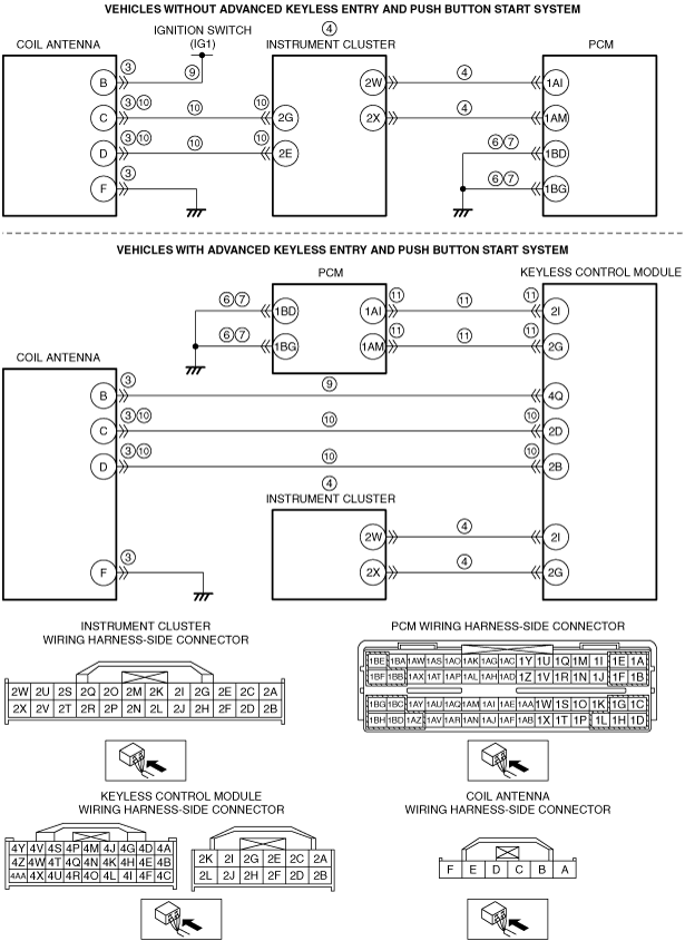
Inspect the following wiring harness:
• Vehicles without advanced keyless entry and push button start system:
-
― Between PCM terminal 1AI and instrument cluster terminal 2W
― Between PCM terminal 1AM and instrument cluster terminal 2X
• Vehicles with advanced keyless entry and push button start system:
-
― Between keyless control module terminal 2I and instrument cluster terminal 2W
― Between keyless control module terminal 2G and instrument cluster terminal 2X
Repair or replace the malfunctioning part according to the inspection results.
|
|
5
|
Retrieve the immobilizer system DTC using the M-MDS.
Are any DTCs present?
|
Yes
|
Go to the applicable DTC inspection.
|
|
No
|
Go to the next step.
|
|
6
|
Switch the ignition to off.
Inspect for continuity between PCM terminals 1AZ, 1BB, 1BD, 1BG, 1BH (wiring harness-side) and body ground.
Is there continuity?
|
Yes
|
Go to the next step.
|
|
No
|
Repair or replace the suspected wiring harness.
|
|
7
|
Switch the ignition to ON (engine off).
Measure the voltage at the PCM terminal 1AZ, 1BB, 1BD, 1BG and 1BH (wiring harness-side).
Is the voltage below 1.0 V?
|
Yes
|
Go to the next step.
|
|
No
|
Repair or replace the suspected wiring harness.
|
|
8
|
Access the VPWR PID using the M-MDS.
Is the VPWR PID value normal?
|
Yes
|
Go to the next step.
|
|
No
|
Repair or replace the malfunctioning part according to the inspection results.
|
|
9
|
Switch the ignition to off.
Disconnect the coil antenna connector.
Switch the ignition to ON (engine off).
Measure the voltage at the coil antenna terminal B (wiring harness-side).
Is the voltage B+?
|
Yes
|
Go to the next step.
|
|
No
|
Repair or replace the suspected wiring harness.
|
|
10
|
Inspect the following wiring harness and connectors:
• Vehicles without advanced keyless entry and push button start system:
-
― Between coil antenna terminal C and instrument cluster terminal 2G
― Between coil antenna terminal D and instrument cluster terminal 2E
• Vehicles with advanced keyless entry and push button start system:
-
― Between coil antenna terminal C and keyless control module terminal 2D
― Between coil antenna terminal D and keyless control module terminal 2B
Is there any malfunction (open or short circuit, terminal corrosion, etc.)?
|
Yes
|
Repair or replace the malfunctioning part according to the inspection results.
|
|
No
|
Vehicles without advanced keyless entry and push button start system:
• Go to Step 12.
Vehicles with advanced keyless entry and push button start system:
• Go to the next step.
|
|
11
|
Inspect the following wiring harness and connectors:
• Between PCM terminal 1AI and keyless control module terminal 2I
• Between PCM terminal 1AM and keyless control module terminal 2G
Is there any malfunction (open or short circuit, terminal corrosion, etc.)?
|
Yes
|
Repair or replace the malfunctioning part according to the inspection results.
|
|
No
|
Go to the next step.
|
|
12
|
Inspect for following:
• Fuel quality (proper octane, contamination, winter/summer blend)
• Intake-air system leakage and restriction
• Electrical connectors
• Poor connection for PCM ground and body ground
• Fuel leakage
• Vacuum leakage
Is there any malfunction?
|
Yes
|
Service if necessary.
• Repeat this step.
|
|
No
|
Go to the next step.
|
|
13
|
Retrieve any PCM DTCs using the M-MDS.
Are any DTCs present?
|
Yes
|
Go to the applicable DTC inspection.
|
|
No
|
Go to the next step.
|
|
14
|
Access the ECT PID using the M-MDS.
Is the ECT PID value less than 116 °C {241 °F} during driving?
|
Yes
|
Go to the next step.
|
|
No
|
The cause of this concern could be from the cooling system overheating.
• Perform the symptom troubleshooting “NO.17 COOLING SYSTEM CONCERNS-OVERHEATING”.
|
|
15
|
Access the VPWR PID using the M-MDS.
Is the VPWR PID value B+?
|
Yes
|
Go to the next step.
|
|
No
|
Repair or replace the wiring harness between main relay terminal C and PCM terminal 1BE and 1BF.
|
|
16
|
Perform the A/C Cut-off Control System Inspection.
Does the A/C cut-off operation work properly?
|
Yes
|
Go to the next step.
|
|
No
|
Repair or replace the malfunctioning part according to the inspection results.
|
|
17
|
Will the engine run smoothly at part throttle?
|
Yes
|
Go to the next step.
|
|
No
|
Go to Step 19.
|
|
18
|
Perform the TP sweep inspection.
Does the electronic throttle control system work properly?
|
Yes
|
Visually inspect the throttle body (damage/scratching).
• If there is any malfunction:
-
― Repair or replace the malfunctioning part according to the inspection results.
• If there is no malfunction:
-
― Go to the next step.
|
|
No
|
Repair or replace the malfunctioning part according to the inspection results.
|
|
19
|
Perform the EGR Control System Inspection.
Does the EGR system operate properly?
|
Yes
|
Go to the next step.
|
|
No
|
Repair or replace the malfunctioning part according to the inspection results.
|
|
20
|
Perform the Purge Control System Inspection.
Does the purge solenoid valve work properly?
|
Yes
|
Go to the next step.
|
|
No
|
Repair or replace the malfunctioning part according to the inspection results.
|
|
21
|
Perform the Variable Valve Timing Control System Operation Inspection.
Does the variable valve timing control system work properly?
|
Yes
|
Go to the next step.
|
|
No
|
Repair or replace the malfunctioning part according to the inspection results.
|
|
22
|
Inspect the CMP sensor and CKP sensor for the following:
• Damaged trigger wheel and camshaft
• Open or short circuit in related circuit
Is there any malfunction?
|
Yes
|
Repair or replace the malfunctioning part according to the inspection results.
|
|
No
|
Go to the next step.
|
|
23
|
-
Caution
-
• While performing this step, always operate the vehicle in a safe and lawful manner.
• When the M-MDS is used to observe monitor system status while driving, be sure to have another technician with you, or record the data in the M-MDS using the PID/DATA MONITOR AND RECORD capturing function and inspect later.
Access the following PIDs using the M-MDS:
• APP
• ECT
• LONGFT1
• MAF
• O2S11
• O2S12
• SHTFT1
Do the PIDs indicate the correct values under the trouble condition?
|
Yes
|
Go to the next step.
|
|
No
|
Repair or replace the malfunctioning part according to the inspection results.
• If the malfunction remains:
-
― Perform the “INTERMITTENT CONCERN TROUBLESHOOTING” procedure.
|
|
24
|
Inspect for restriction in the exhaust system and the TWC.
Is there any restriction?
|
Yes
|
Repair or replace the malfunctioning part according to the inspection results.
|
|
No
|
Go to the next step.
|
|
25
|
Perform the Spark Test.
Is a strong blue spark visible at each cylinder?
|
Yes
|
Go to the next step.
|
|
No
|
Repair or replace the malfunctioning part according to the inspection results.
|
|
26
|
Access the FUEL_PRES PID using the M-MDS.
Is the FUEL_PRES PID value within the specification?
|
Yes
|
Go to Step 31.
|
|
No
|
Go to the next step.
|
|
27
|
Is the vehicle accelerate performance normally?
|
Yes
|
Go to the next step.
|
|
No
|
Go to Step 29.
|
|
28
|
Inspect the fuel pressure sensor.
Is there any malfunction?
|
Yes
|
Replace the fuel delivery pipe.
|
|
No
|
Go to Step 31.
|
|
29
|
Switch the ignition to off.
Disconnect the high pressure fuel pump and PCM connectors.
Inspect for continuity between high pressure fuel pump terminal A (wiring harness-side) and body ground.
Is there continuity?
|
Yes
|
Repair or replace the wiring harness for a possible short to ground.
• If the malfunction remains:
-
― Replace the PCM. (damage to driver in PCM)
|
|
No
|
Go to the next step.
|
|
30
|
Replace the high pressure fuel pump.
Access the FUEL_PRES PID using the M-MDS.
Is the FUEL_PRES PID value within the specification?
|
Yes
|
High pressure fuel pump or spill valve control solenoid valve (built-in high pressure fuel pump) malfunction.
• Symptom troubleshooting is completed.
• Go to Step 35.
|
|
No
|
Relief valve (built-in fuel delivery pipe) malfunction.
• Replace the fuel delivery pipe.
|
|
31
|
Connect the fuel pressure gauge between fuel pump and high pressure fuel pump.
Measure the low side fuel pressure.
Is the low side fuel pressure within the specification?
|
Yes
|
Go to the next step.
|
|
No
|
Inspect for following:
• Fuel line restriction
• Fuel filter clogging
-
― If there is any malfunction:
-
• Repair or replace the malfunctioning part according to the inspection results.
― If there is no malfunction:
-
• Replace the fuel pump unit.
|
|
32
|
Perform the Fuel Injector Operation Inspection.
Do the fuel injectors operate properly?
|
Yes
|
Go to the next step.
|
|
No
|
Repair or replace the malfunctioning part according to the inspection results.
|
|
33
|
Measure the compression pressure for each cylinder.
Are the compression pressures within the specification?
|
Yes
|
Go to the next step.
|
|
No
|
Inspect for following:
• Damaged valve seat
• Worn valve stem and valve guide
• Worn or stuck piston ring
• Worn piston, piston ring or cylinder
• Improper valve timing
Service if necessary.
|
|
34
|
Inspect the PCV valve.
Is there any malfunction?
|
Yes
|
Replace the PCV valve.
|
|
No
|
Injector driver is malfunction.
If the malfunction remains:
• Overhaul the engine.
|
|
35
|
Verify the test results.
• If a malfunction remains, inspect the related Service Information and perform the repair or diagnosis.
-
― If the vehicle is repaired, troubleshooting is completed.
|