 |
am6zzw00004191
ENGINE REMOVAL/INSTALLATION [MZR-CD 2.2]
id0110f2800400
|
STEP |
ACTION |
PAGE/CONDITION |
|---|---|---|
|
1
|
Replace the timing chain.
|
—
|
|
2
|
Start the engine.
|
—
|
|
3
|
Perform the injection amount correction procedure.
|
Engine coolant temperature: 65—95 °C {149—203 °F}
Intake air temperature: 15—65 °C {59—149 °F}
Fuel temperature: 30—60 °C {86—140 °F}
|
|
4
|
Perform the timing chain correction procedure.
|
Engine coolant temperature: 65—95 °C {149—203 °F}
Intake air temperature: 15—65 °C {59—149 °F}
Fuel temperature: 30—60 °C {86—140 °F}
|
|
5
|
Perform after repair procedure.
|
|
|
6
|
Switch the ignition to off.
|
—
|
1. Drain the engine coolant. (See ENGINE COOLANT REPLACEMENT [MZR-CD 2.2].)
2. Drain the transaxle oil. (See TRANSAXLE OIL REPLACEMENT [A26M-R].)
3. Remove the engine cover. (See ENGINE COVER REMOVAL/INSTALLATION [MZR-CD 2.2].)
4. Remove the battery and battery tray. (See BATTERY REMOVAL/INSTALLATION [MZR-CD 2.2].)
5. Remove the air cleaner component and air inlet hose. (See INTAKE-AIR SYSTEM REMOVAL/INSTALLATION [MZR-CD 2.2].)
6. Remove the boost sensor. (See COMMON RAIL REMOVAL/INSTALLATION [MZR-CD 2.2].)
7. Remove the dipstick.
8. Disconnect the fuel main hose and fuel return hose.
9. Disconnect the vacuum hose. (See VACUUM HOSE REMOVAL/INSTALLATION [MZR-CD 2.2].)
10. Disconnect the heater hoses.
11. Disconnect the upper radiator hose.
12. Disconnect the charge air cooler inlet hose and charge air cooler outlet hose. (See INTAKE-AIR SYSTEM REMOVAL/INSTALLATION [MZR-CD 2.2].)
13. Set the shift cable, selector cable and clutch release cylinder parts related to the transaxle out of the way. (See MANUAL TRANSAXLE REMOVAL/INSTALLATION [A26M-R].)
14. Remove the front wheels and tires. (See GENERAL PROCEDURES (SUSPENSION).)
15. Remove the aerodynamic under cover No.2. (See AERODYNAMIC UNDER COVER NO.2 REMOVAL/INSTALLATION.)
16. Remove the aerodynamic under cover No.1. (See AERODYNAMIC UNDER COVER NO.1 REMOVAL/INSTALLATION.)
17. Set the front mudguards out of the way. (See FRONT MUDGUARD REMOVAL/INSTALLATION.)
18. Remove the splash shields.
19. Remove the front crossmember component. (See FRONT CROSSMEMBER REMOVAL/INSTALLATION.)
20. Disconnect the front drive shaft from the transaxle. (See DRIVE SHAFT REMOVAL/INSTALLATION.)
21. Remove the thermostat. (See THERMOSTAT REMOVAL/INSTALLATION [MZR-CD 2.2].)
22. Remove the drive belt. (See DRIVE BELT REMOVAL/INSTALLATION [MZR-CD 2.2].)
23. Remove the A/C compressor with the pipe still connected. Set the A/C compressor out of the way. Use wire or rope to secure it. (See A/C COMPRESSOR REMOVAL/INSTALLATION.)
24. Remove the oxidation catalytic converter (built-in diesel particulate filter). (See EXHAUST SYSTEM REMOVAL/INSTALLATION [MZR-CD 2.2].)
25. Remove the front pipe. (See EXHAUST SYSTEM REMOVAL/INSTALLATION [MZR-CD 2.2].)
26. Disconnect the exhaust gas pressure hoses. (See EXHAUST GAS PRESSURE SENSOR/EXHAUST GAS PRESSURE CORRECTION TEMPERATURE SENSOR REMOVAL/INSTALLATION [MZR-CD 2.2].)
27. Remove the seal plate. (See OIL PAN REMOVAL/INSTALLATION [MZR-CD 2.2].)
28. Disconnect the wiring harness.
29. Remove in the order shown in the table.
30. Install in the reverse order of removal.
31. Refill the engine coolant. (See ENGINE COOLANT REPLACEMENT [MZR-CD 2.2].)
32. Refill the transaxle oil. (See TRANSAXLE OIL REPLACEMENT [A26M-R].)
33. Start the engine and:
34. Perform a road test.
35. Reinspect the engine oil, engine coolant, transaxle oil.
am6zzw00004191
|
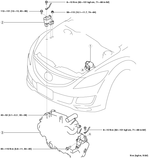
|
1
|
No.4 engine mount rubber
|
|
2
|
No.3 engine mount bracket
|
|
3
|
Engine, transaxle
|
No.3 Engine Mount Bracket, No.4 Engine Mount Rubber Removal Note
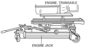
1. Secure the engine and transaxle using an engine jack.
am6zzw00007982
|
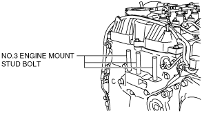
Engine Mount Installation Note
1. Tighten the No.3 engine mount stud bolts.
am6zzw00004192
|
2. Secure the engine and transaxle using an engine jack.
am6zzw00007982
|
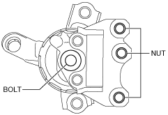
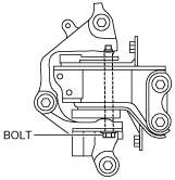
3. Temporarily tighten the bolt and nuts shown in the figure.
am6zzw00004317
|
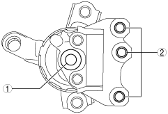
4. Tighten the bolt and nuts in the order shown in the figure.
am6zzw00004318
|
5. Tighten the bolt shown in the figure.
am6zzw00004195
|