 |
am6zzw00004850
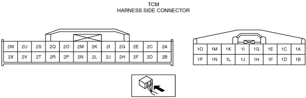
TCM INSPECTION [FS5A-EL]
id051721800300
1. Disconnect the negative battery cable.
2. Remove the TCM. (See TCM REMOVAL/INSTALLATION [FS5A-EL].)
3. Connect the TCM connector.
4. Connect the negative battery cable.
5. Connect the voltmeter (–) lead to body GND.
6. Measure the voltage at each terminal.
Terminal Voltage Table (Reference)
am6zzw00004850
|
|
Terminal |
Connected to |
Test condition |
Voltage (V) |
Action |
|---|---|---|---|---|
|
1A
|
Shift solenoid A
|
(See Shift solenoid A.)
|
• Shift solenoid A
• Related harness
|
|
|
1B
|
Shift solenoid B
|
(See Shift solenoid B.)
|
• Shift solenoid B
• Related harness
|
|
|
1C
|
Shift solenoid C
|
(See Shift solenoid C.)
|
• Shift solenoid C
• Related harness
|
|
|
1D
|
Pressure control solenoid B
|
(See Pressure control solenoid B.)
|
• Pressure control solenoid B
• Related harness
|
|
|
1E
|
Pressure control solenoid A (+)
|
• Pressure control solenoid A
• Related harness
|
||
|
1F
|
Shift solenoid D
|
D range 1GR
|
Below 1.0
|
• Shift solenoid D
• Related harness
|
|
D range 2GR
|
Below 1.0
|
|||
|
D range 3GR
|
Below 1.0
|
|||
|
D range 4GR
|
B+
|
|||
|
D range 5GR
|
B+
|
|||
|
1G
|
Pressure control solenoid A (–)
|
• Pressure control solenoid A
• Related harness
|
||
|
1H
|
Shift solenoid E
|
TCC released
|
Below 1.0
|
• Shift solenoid E
• Related harness
|
|
TCC engaged
|
B+
|
|||
|
1I
|
—
|
—
|
—
|
—
|
|
1J
|
Shift solenoid F
|
D range 1GR
|
B+
|
• Shift solenoid F
• Related harness
|
|
D range 2GR
|
B+
|
|||
|
D range 3GR
|
B+
|
|||
|
D range 4GR
|
B+
|
|||
|
D range 5GR
|
Below 1.0
|
|||
|
1K
|
Battery
|
Under any condition
|
B+
|
• Battery
• Related harness
|
|
1L
|
—
|
—
|
—
|
—
|
|
1M
|
AT Main relay
|
Switch the ignition to off
|
Below 1.0
|
• AT Main relay
(See RELAY INSPECTION.)
• Related harness
|
|
Switch the ignition to ON
|
B+
|
|||
|
1N
|
AT Main relay
|
Switch the ignition to off
|
Below 1.0
|
• AT Main relay
(See RELAY INSPECTION.)
• Related harness
|
|
Switch the ignition to ON
|
B+
|
|||
|
1O
|
GND
|
Under any condition
|
Below 1.0
|
• Related harness
|
|
1P
|
GND
|
Under any condition
|
Below 1.0
|
• Related harness
|
|
2A
|
—
|
—
|
—
|
—
|
|
2B
|
M range switch
|
M range
|
Below 1.0
|
• M range switch
• Related harness
|
|
Except M range
|
B+
|
|||
|
2C
|
—
|
—
|
—
|
—
|
|
2D
|
Up switch
|
Selector lever up-shift position
|
Below 1.0
|
• Up switch
• Related harness
|
|
Except selector lever up-shift position
|
B+
|
|||
|
2E
|
—
|
—
|
—
|
—
|
|
2F
|
Down switch
|
Selector lever down-shift position
|
Below 1.0
|
• Down switch
• Related harness
|
|
Except selector lever down-shift position
|
B+
|
|||
|
2G
|
—
|
—
|
—
|
—
|
|
2H
|
TR switch
|
P position
|
4.3—4.8
|
• TR switch
• Related harness
|
|
R position
|
3.8—4.2
|
|||
|
N position
|
3.0—3.5
|
|||
|
D range
|
2.2—2.7
|
|||
|
M range
|
2.2—2.7
|
|||
|
2I
|
Input/turbine speed sensor (+)
|
(See Input/turbine speed sensor.)
|
• Input/turbine speed sensor
• Related harness
|
|
|
2J
|
Oil pressure switch
|
1GR
|
Below 1.0
|
• Oil pressure switch
• Related harness
|
|
2GR
|
Below 1.0
|
|||
|
3GR
|
Below 1.0
|
|||
|
4GR
|
B+
|
|||
|
5GR
|
B+
|
|||
|
2K
|
Input/turbine speed sensor (-)
|
(See Input/turbine speed sensor.)
|
• Input/turbine speed sensor
• Related harness
|
|
|
2L
|
Intermediate sensor
|
(See Intermediate sensor.)
|
• Intermediate sensor
• Related harness
|
|
|
2M
|
TFT sensor
|
ATF temperature 20 °C
|
Approx. 3.3
|
• TFT sensor
• Related harness
|
|
ATF temperature 65 °C
|
Approx. 1.3
|
|||
|
2N
|
Steering shift switch
|
Under any condition
|
Below 1.0
|
• Related harness
|
|
2O
|
TFT sensor, TR switch
|
Under any condition
|
Below 1.0
|
• Related harness
|
|
2P
|
VSS
|
(See VSS.)
|
• VSS
• Related harness
|
|
|
2Q
|
Steering shift switch
|
Up switch and down switch released
(Steering shift switch)
|
Approx. 5.0
|
• Steering shift switch
• Related harness
|
|
Up switch operated
(Steering shift switch)
|
Approx. 2.8
|
|||
|
Down switch operated
(Steering shift switch)
|
Approx. 2.2
|
|||
|
2R
|
AT Main relay
|
Switch the ignition to off
|
Below 1.0
|
• AT main relay
(See RELAY INSPECTION.)
• Related harness
|
|
Switch the ignition to ON
|
Approx. 0.8
|
|||
|
2S
|
—
|
—
|
—
|
—
|
|
2T
|
—
|
—
|
—
|
—
|
|
2U
|
—
|
—
|
—
|
—
|
|
2V
|
—
|
—
|
—
|
—
|
|
2W
|
CAN module
|
Because this terminal is for CAN, no valid determination of terminal voltage is possible.
|
||
|
2X
|
CAN module
|
Because this terminal is for CAN, no valid determination of terminal voltage is possible.
|
||
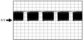
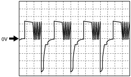
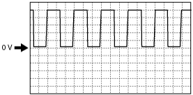
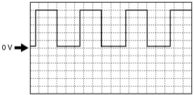
Input/Output Wave From (Reference)
Shift solenoid A
am6zzw00007176
|
Shift solenoid B
am6zzw00007176
|
Shift solenoid C
am6zzw00007176
|
Pressure control solenoid B
am6zzw00004856
|
Pressure control solenoid A (+)
am6zzw00004855
|
Pressure control solenoid A (–)
am6zzw00007177
|
Input/turbine speed sensor
am6zzw00006790
|
Intermediate sensor
am6zzw00004851
|
VSS
am6zzw00006795
|