 |
am6zzw00006025
DTC U3003:16, U3003:17 [REAR VEHICLE MONITORING SYSTEM]
id0902z2884400
|
DESCRIPTION |
Rear vehicle monitoring control module (RH) power supply circuit malfunction |
|---|---|
|
DETECTION CONDITION
|
U3003:16
• Rear vehicle monitoring control module (RH) power supply voltage is less than 9 V.
U3003:17
• Rear vehicle monitoring control module (RH) power supply voltage is 16 V or more.
|
|
POSSIBLE CAUSE
|
• Battery malfunction
• Generator malfunction
• Rear vehicle monitoring control module (RH) connector or terminals malfunction
• Short to ground or open circuit in rear vehicle monitoring control module (RH) power supply circuit
• Rear vehicle monitoring control module (RH) malfunction
|
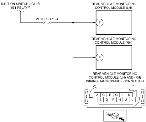
System Wiring Diagram
am6zzw00006025
|
Diagnostic Procedure
|
STEP |
INSPECTION |
ACTION |
|
|---|---|---|---|
|
1
|
VERIFY PCM DTCs
• Verify the PCM DTCs using the M-MDS.
• Are any DTCs present?
|
Yes
|
Go to the applicable DTC inspection.
(See DTC TABLE [MZR 2.0 DISI].)
(See DTC TABLE [MZR-CD 2.2].)
|
|
No
|
Go to the next step.
|
||
|
2
|
INSPECT BATTERY
• Inspect the battery.
• Is there any malfunction?
|
Yes
|
Recharge or replace the battery, then go to Step 6.
|
|
No
|
Go to the next step.
|
||
|
3
|
INSPECT GENERATOR
• Inspect the generator.
• Is there any malfunction?
|
Yes
|
Replace the generator, then go to Step 6.
|
|
No
|
Go to the next step.
|
||
|
4
|
INSPECT REAR VEHICLE MONITORING CONTROL MODULE (RH) CONNECTOR AND TERMINALS
• Switch the ignition to off.
• Disconnect the negative battery cable.
• Disconnect the rear vehicle monitoring control module (RH) connector.
• Inspect the connector and terminals (corrosion, damage, pin disconnection).
• Is there any malfunction?
|
Yes
|
Repair or replace the connector or terminals, then go to Step 6.
|
|
No
|
Go to the next step.
|
||
|
5
|
INSPECT REAR VEHICLE MONITORING CONTROL MODULE (RH) CIRCUIT FOR SHORT TO GROUND OR OPEN CIRCUIT
• Rear vehicle monitoring control module (RH) connector is disconnected.
• Reconnect the negative battery cable.
• Switch the ignition to ON.
• Measure the voltage at the rear vehicle monitoring control module (RH) terminal F (wiring harness-side).
• Is the voltage B+?
|
Yes
|
Go to the next step.
|
|
No
|
Inspect the METER IG 15 A fuse.
• If the fuse is melt:
• If the fuse is deterioration:
• If the fuse is normal:
Go to the next step.
|
||
|
6
|
VERIFY TROUBLESHOOTING COMPLETED
• Make sure to reconnect all disconnected connectors.
• Reconnect the negative battery cable.
• Clear the DTC from the rear vehicle monitoring control module using the M-MDS.
• Verify the rear vehicle monitoring system DTC using the M-MDS.
• Is the same DTC present?
|
Yes
|
Replace the rear vehicle monitoring control module (RH), then go to the next step.
|
|
No
|
Go to the next step.
|
||
|
7
|
VERIFY THAT NO OTHER DTCs ARE PRESENT
• Are any DTCs present?
|
Yes
|
Go to the applicable DTC inspection.
|
|
No
|
DTC troubleshooting completed.
|
||