ANTENNA FEEDER NO.3 REMOVAL/INSTALLATION
id092000812900
4SD
1. Disconnect the negative battery cable.
2. Partially peel back the seaming welt.
3. Remove the following parts:
- (1) Sunroof seaming welt (vehicles with sunroof only)
- (2) A-pillar trim (See A-PILLAR TRIM REMOVAL/INSTALLATION.)
- (3) Upper anchor of the front seat belt (See FRONT SEAT BELT REMOVAL/INSTALLATION.)
- (4) Front scuff plate (See FRONT SCUFF PLATE REMOVAL/INSTALLATION.)
- (5) Rear scuff plate (See REAR SCUFF PLATE REMOVAL/INSTALLATION.)
- (6) B-pillar lower trim (See B-PILLAR LOWER TRIM REMOVAL/INSTALLATION.)
- (7) B-pillar upper trim (See B-PILLAR UPPER TRIM REMOVAL/INSTALLATION.)
- (8) Rear seat cushion (See REAR SEAT CUSHION REMOVAL/INSTALLATION [4SD].)
- (9) Rear side seat back (See REAR SIDE SEAT BACK REMOVAL/INSTALLATION.)
- (10) Tire house trim (See TIRE HOUSE TRIM REMOVAL/INSTALLATION.)
- (11) C-pillar trim (See C-PILLAR TRIM REMOVAL/INSTALLATION.)
- (12) Sunvisor (See SUNVISOR REMOVAL/INSTALLATION.)
- (13) Map light (See MAP LIGHT REMOVAL/INSTALLATION.)
- (14) Assist handle (See ASSIST HANDLE REMOVAL/INSTALLATION.)
- (15) Headliner (See HEADLINER REMOVAL/INSTALLATION.)
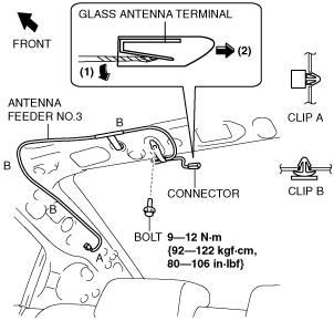
4. Remove the connector in the direction of the arrow (2) shown in the figure while pressing the glass antenna terminal in the direction of the arrow (1).
5. Remove the clips A and B.
6. Remove the bolt.
7. Remove the antenna feeder No.3.
8. Install in the reverse order of removal.
5HB
1. Disconnect the negative battery cable.
2. Partially peel back the seaming welt.
3. Remove the following parts:
- (1) Sunroof seaming welt (vehicles with sunroof only)
- (2) A-pillar trim (See A-PILLAR TRIM REMOVAL/INSTALLATION.)
- (3) Upper anchor of the front seat belt (See FRONT SEAT BELT REMOVAL/INSTALLATION.)
- (4) Front scuff plate (See FRONT SCUFF PLATE REMOVAL/INSTALLATION.)
- (5) Rear scuff plate (See REAR SCUFF PLATE REMOVAL/INSTALLATION.)
- (6) B-pillar lower trim (See B-PILLAR LOWER TRIM REMOVAL/INSTALLATION.)
- (7) B-pillar upper trim (See B-PILLAR UPPER TRIM REMOVAL/INSTALLATION.)
- (8) Tire house trim (See TIRE HOUSE TRIM REMOVAL/INSTALLATION.)
- (9) Trunk side upper trim (See TRUNK SIDE UPPER TRIM REMOVAL/INSTALLATION.)
- (10) Rear seat (See REAR SEAT REMOVAL/INSTALLATION [5HB/WAGON].)
- (11) Lower anchor of the rear seat belt installation bolts (LH) (See REAR SEAT BELT REMOVAL/INSTALLATION [5HB, WGN].)
- (12) C-pillar trim (See C-PILLAR TRIM REMOVAL/INSTALLATION.)
- (13) Sunvisor (See SUNVISOR REMOVAL/INSTALLATION.)
- (14) Map light (See MAP LIGHT REMOVAL/INSTALLATION.)
- (15) Assist handle (See ASSIST HANDLE REMOVAL/INSTALLATION.)
- (16) Headliner (See HEADLINER REMOVAL/INSTALLATION.)
- (17) Liftgate upper trim (See LIFTGATE UPPER TRIM REMOVAL/INSTALLATION.)
4. Disconnect the antenna amplifier connector. (See ANTENNA AMPLIFIER REMOVAL/INSTALLATION.)
5. Partially peel back the grommet.
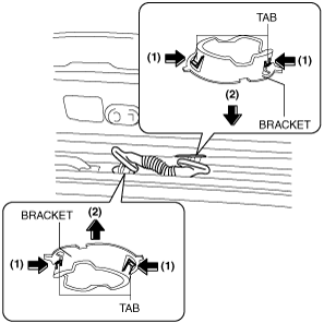
6. Remove the bracket in the direction of the arrow (2) shown in the figure while pressing the bracket tabs in the direction of the arrow (1).
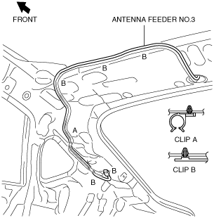
7. Remove the clips A and B.
8. Remove antenna feeder No.3.
9. Install in the reverse order of removal.
WGN
1. Disconnect the negative battery cable.
2. Partially peel back the seaming welt.
3. Remove the following parts:
- (1) Sunroof seaming welt (vehicles with sunroof only)
- (2) A-pillar trim (See A-PILLAR TRIM REMOVAL/INSTALLATION.)
- (3) Upper anchor of the front seat belt (See FRONT SEAT BELT REMOVAL/INSTALLATION.)
- (4) Front scuff plate (See FRONT SCUFF PLATE REMOVAL/INSTALLATION.)
- (5) Rear scuff plate (See REAR SCUFF PLATE REMOVAL/INSTALLATION.)
- (6) B-pillar lower trim (See B-PILLAR LOWER TRIM REMOVAL/INSTALLATION.)
- (7) B-pillar upper trim (See B-PILLAR UPPER TRIM REMOVAL/INSTALLATION.)
- (8) Tire house trim (See TIRE HOUSE TRIM REMOVAL/INSTALLATION.)
- (9) Trunk side upper trim (See TRUNK SIDE UPPER TRIM REMOVAL/INSTALLATION.)
- (10) Rear seat (See REAR SEAT REMOVAL/INSTALLATION [5HB/WAGON].)
- (11) Lower anchor of the rear seat belt installation bolts (LH) (See REAR SEAT BELT REMOVAL/INSTALLATION [5HB, WGN].)
- (12) C-pillar trim (See C-PILLAR TRIM REMOVAL/INSTALLATION.)
- (13) D-pillar trim (See D-PILLAR TRIM REMOVAL/INSTALLATION.)
- (14) Sunvisor (See SUNVISOR REMOVAL/INSTALLATION.)
- (15) Map light (See MAP LIGHT REMOVAL/INSTALLATION.)
- (16) Assist handle (See ASSIST HANDLE REMOVAL/INSTALLATION.)
- (17) Headliner (See HEADLINER REMOVAL/INSTALLATION.)
- (18) Liftgate upper trim (See LIFTGATE UPPER TRIM REMOVAL/INSTALLATION.)
4. Disconnect the antenna feeder No.4 connector. (See ANTENNA FEEDER NO.4 REMOVAL/INSTALLATION.)
5. Partially peel back the grommet.
6. Remove the bracket in the direction of the arrow (2) shown in the figure while pressing the bracket tabs in the direction of the arrow (1).
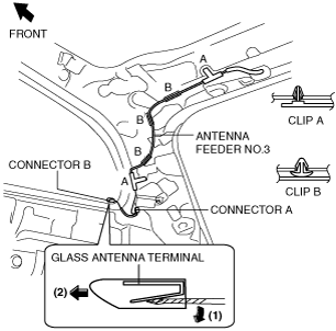
7. Disconnect the connector A.
8. Remove the connector B in the direction of the arrow (2) shown in the figure while pressing the glass antenna terminal in the direction of the arrow (1).
9. Remove the clips A and B.
10. Remove antenna feeder No.3.
11. Install in the reverse order of removal.