|
am6zzw00003539
ANTENNA FEEDER NO.3 INSPECTION
id092000813000
4SD
1. Disconnect the negative battery cable.
2. Remove the following parts:
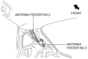
3. Disconnect antenna feeder No.2.
am6zzw00003539
|
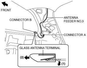
4. Disconnect the connector in the direction of the arrow (2) shown in the figure while pressing the glass antenna terminal in the direction of the arrow (1).
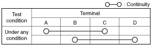
5. Verify that the continuity between antenna feeder No.3 terminals is as indicated in the table.
am6zzw00006819
|
am6zzw00006820
|
5HB
1. Disconnect the negative battery cable.
2. Remove the following parts:
3. Disconnect the antenna amplifier connector. (See ANTENNA AMPLIFIER REMOVAL/INSTALLATION.)
4. Disconnect antenna feeder No.2.
am6zzw00002011
|
5. Verify that the continuity between antenna feeder No.3 terminals is as indicated in the table.
am6zzw00006821
|
am6zzw00006822
|
WGN
1. Disconnect the negative battery cable.
2. Remove the following parts:
3. Disconnect the antenna feeder No.4. (See ANTENNA FEEDER NO.4 REMOVAL/INSTALLATION.)
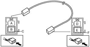
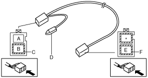
4. Disconnect the connector A.
am6zzw00003238
|
5. Disconnect the connector B in the direction of the arrow (2) shown in the figure while pressing the glass antenna terminal in the direction of the arrow (1).
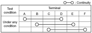
6. Verify that the continuity between antenna feeder No.3 terminals is as indicated in the table.
am6zzw00006823
|
am6zzw00006822
|