|
1
|
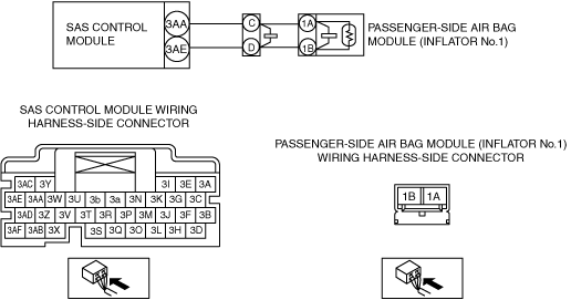
INSPECT PASSENGER-SIDE AIR BAG MODULE (INFLATOR No.1) CONNECTOR
-
Warning
-
• Handling the component parts improperly can accidentally operate (deploy) the air bag module, which may seriously injure you. Read the service warnings/cautions and the workshop manual before handling the air bag system components.
• Switch the ignition off.
• Inspect the passenger-side air bag module (inflator No.1) connector (wiring harness-side). (Corrosion, damage, and disconnected pins)
• Is there any malfunction of the passenger-side air bag module (inflator No.1) connector (wiring harness-side)?
|
Yes
|
Replace the malfunctioning part, then go to Step 8.
|
|
No
|
Go to the next step.
|
|
2
|
INSPECT PASSENGER-SIDE AIR BAG MODULE (INFLATOR No.1) CIRCUIT FOR SHORT TO GROUND
• Disconnect the passenger-side air bag module (inflator No.2) connector.
• Disconnect the active bonnet actuator connector.
• Inspect for continuity between the following terminals (wiring harness-side) and body ground:
-
― SAS control module terminal 3AA
― SAS control module terminal 3AE
-
Note
-
• Inspect for continuity while shaking the wiring harness between the SAS control module and passenger-side air bag module.
• Is there continuity?
|
Yes
|
Refer to the wiring diagram and verify whether or not there is a common connector between SAS control module terminal and passenger-side air bag module (inflator No.1) terminal.
If there is a common connector:
• Determine the malfunctioning part by inspecting the common connector and the terminal for corrosion, damage, or pin disconnection, and the common wiring harness for a short to ground.
• Replace the malfunctioning part.
If there is no common connector:
• Replace the wiring harness which has a short to ground.
Go to Step 8.
|
|
No
|
Go to the next step.
|
|
3
|
INSPECT PASSENGER-SIDE AIR BAG MODULE (INFLATOR No.1) CIRCUIT FOR OPEN CIRCUIT
• Passenger-side air bag module (inflator No.1) and SAS control module connectors are disconnected.
• Inspect for continuity between the following terminals (wiring harness-side):
-
― Passenger-side air bag module terminal 1A—SAS control module terminal 3AA
― Passenger-side air bag module terminal 1B—SAS control module terminal 3AE
-
Note
-
• Inspect for continuity while shaking the wiring harness between the SAS control module and passenger-side air bag module.
• Is there continuity?
|
Yes
|
Go to the next step.
|
|
No
|
Refer to the wiring diagram and verify whether or not there is a common connector between SAS control module terminal and passenger-side air bag module (inflator No.1) terminal.
If there is a common connector:
• Determine the malfunctioning part by inspecting the common connector and the terminal for corrosion, damage, or pin disconnection, and the common wiring harness for an open circuit.
• Replace the malfunctioning part.
If there is no common connector:
• Replace the wiring harness which has an open circuit.
Go to Step 8.
|
|
4
|
INSPECT PASSENGER-SIDE AIR BAG MODULE (INFLATOR No.1) CIRCUIT FOR SHORT TO EACH OTHER
• Passenger-side air bag module (inflator No.1) and SAS control module connectors are disconnected.
• Inspect for continuity between the following terminals (wiring harness-side):
-
― SAS control module terminal 3AE—SAS control module terminal 3AA
-
Note
-
• Inspect for continuity while shaking the wiring harness between the SAS control module and passenger-side air bag module.
• Is there continuity?
|
Yes
|
Refer to the wiring diagram and verify whether or not there is a common connector between SAS control module terminal and passenger-side air bag module (inflator No.1) terminal.
If there is a common connector:
• Determine the malfunctioning part by inspecting the common connector and the terminal for corrosion, damage, or pin disconnection, and the common wiring harness for a short to each other.
• Replace the malfunctioning part.
If there is no common connector:
• Replace the wiring harness which has a short to each other.
Go to Step 8.
|
|
No
|
Go to the next step.
|
|
5
|
INSPECT PASSENGER-SIDE AIR BAG MODULE (INFLATOR No.1) CIRCUIT FOR SHORT TO OTHER AIR BAG MODULE OR ACTIVE BONNET ACTUATOR CIRCUIT
• Passenger-side air bag module (inflator No.1) and SAS control module connectors are disconnected.
• Other air bag module, active bonnet actuator and pre-tensioner seat belt connectors are disconnected.
• Refer to the wiring diagram and inspect for continuity between the following terminals and other air bag module / active bonnet actuator / pre-tensioner seat belt terminals (wiring harness-side).
-
― SAS control module terminal 3AA
― SAS control module terminal 3AE
-
Note
-
• Inspect for continuity while shaking the wiring harness between the SAS control module and passenger-side air bag module.
• Is there continuity?
|
Yes
|
Refer to the wiring diagram and verify whether or not there is a common connector between SAS control module terminal and passenger-side air bag module (inflator No.1) terminal.
If there is a common connector:
• Determine the malfunctioning part by inspecting the common connector and the terminal for corrosion, damage, or pin disconnection, and the common wiring harness for a short to other air bag module or active bonnet actuator or pre-tensioner seat belt circuit.
• Replace the malfunctioning part.
If there is no common connector:
• Replace the wiring harness which has a short to other air bag module or active bonnet actuator or pre-tensioner seat belt circuit.
Go to Step 8.
|
|
No
|
Go to the next step.
|
|
6
|
INSPECT PASSENGER-SIDE AIR BAG MODULE (INFLATOR No.1) CIRCUIT FOR SHORT TO POWER SUPPLY
• Passenger-side air bag module (inflator No.1) and SAS control module connectors are disconnected.
• Switch the ignition ON (engine off or on).
• Measure the voltage at the following terminals (wiring harness-side):
-
― SAS control module terminal 3AA
― SAS control module terminal 3AE
-
Note
-
• Measure the voltage while shaking the wiring harness between the SAS control module and passenger-side air bag module.
• Is the voltage 0 V?
|
Yes
|
Go to the next step.
|
|
No
|
Refer to the wiring diagram and verify whether or not there is a common connector between SAS control module terminal and passenger-side air bag module (inflator No.1) terminal.
If there is a common connector:
• Determine the malfunctioning part by inspecting the common connector and the terminal for corrosion, damage, or pin disconnection, and the common wiring harness for a short to power supply.
• Replace the malfunctioning part.
If there is no common connector:
• Replace the wiring harness which has a short to power supply.
Go to Step 8.
|
|
7
|
INSPECT PASSENGER-SIDE AIR BAG MODULE (INFLATOR No.1)
• Disconnect the negative battery terminal and wait for 1 min or more.
• Connect the SAS control module connectors.
• Except for the passenger-side air bag module (inflator No.1) connector, reconnect all disconnected connectors.
• Apply 2 ohms resistance to the passenger-side air bag module connector (inflator No.1) terminals 1A and 1B (wiring harness-side).
• Switch the ignition ON (engine off or on).
• Are the same Pending DTCs present?
|
Yes
|
Go to the next step.
|
|
No
|
Then go to the next step.
|
|
8
|
PERFORM SAS CONTROL MODULE DTC INSPECTION
• Switch the ignition off.
• Disconnect the negative battery terminal and wait for 1 min or more.
• Disconnect the 2 ohms resistance.
• Connect the passenger-side air bag module (inflator No.1) connector.
• Switch the ignition ON (engine off or on).
• Are the same Pending DTCs present?
|
Yes
|
Repeat the inspection from Step 1.
• If the malfunction recurs, replace the SAS control module.
|
|
No
|
DTC troubleshooting completed.
|