 |
am6zzw00003835
ENGINE REMOVAL/INSTALLATION [MZR-CD (RF Turbo)]
id0110f1800400
1. Remove the engine cover. (See TIMING BELT REMOVAL/INSTALLATION [MZR-CD (RF Turbo)].)
2. Remove the battery and tray. (See BATTERY REMOVAL/INSTALLATION [MZR-CD (RF Turbo)].)
3. Remove the air cleaner and air hose. (See INTAKE-AIR SYSTEM REMOVAL/INSTALLATION [MZR-CD (RF Turbo)].)
4. Disconnect the fuel hose. (See BEFORE SERVICE PRECAUTION [MZR-CD (RF Turbo)].)
5. Remove the both front tires.
6. Remove the aerodynamic under cover No.2. (See AERODYNAMIC UNDER COVER NO.2 REMOVAL/INSTALLATION.)
7. Set the front mudguards out of the way. (See FRONT MUDGUARD REMOVAL/INSTALLATION.)
8. Remove the splash shields.
9. Remove the drive belt. (See DRIVE BELT REMOVAL/INSTALLATION [MZR-CD (RF Turbo)].)
10. Remove the front crossmember. (See FRONT CROSSMEMBER REMOVAL/INSTALLATION.)
11. Remove the oxidation catalytic converter. (See EXHAUST SYSTEM REMOVAL/INSTALLATION [MZR-CD (RF Turbo)].)
12. Disconnect the front pipe. (See EXHAUST SYSTEM REMOVAL/INSTALLATION [MZR-CD (RF Turbo)].)
13. Drain the engine coolant and transaxle oil.
14. Disconnect the front drive shaft from the transaxle. (See DRIVE SHAFT REMOVAL/INSTALLATION.)
15. Disconnect the radiator hose. (See RADIATOR REMOVAL/INSTALLATION [MZR-CD (RF Turbo)].)
16. Set the shift cable, select cable and clutch release cylinder parts related to the transaxle out of the way. (See MANUAL TRANSAXLE REMOVAL/INSTALLATION [A26M-R (MZR-CD (RF Turbo))].)
17. Remove the A/C compressor with the pipe still connected. Set the A/C compressor out of the way. Use wire or rope to secure it. (See A/C COMPRESSOR REMOVAL/INSTALLATION.)
18. Remove the coolant reserve tank. (See COOLANT RESERVE TANK REMOVAL/INSTALLATION [MZR-CD (RF Turbo)].)
19. Remove the starter. (See STARTER REMOVAL/INSTALLATION [MZR-CD (RF Turbo)].)
20. Disconnect the vacuum hose and the heater hose.
21. Remove PTC heater. (With PTC heater) (See PTC (POSITIVE TEMPERATURE COEFFICIENT) HEATER REMOVAL/INSTALLATION [FULL-AUTO AIR CONDITIONER].) (See PTC (POSITIVE TEMPERATURE COEFFICIENT) HEATER REMOVAL/INSTALLATION [MANUAL AIR CONDITIONER].)
22. Disconnect the wiring harness.
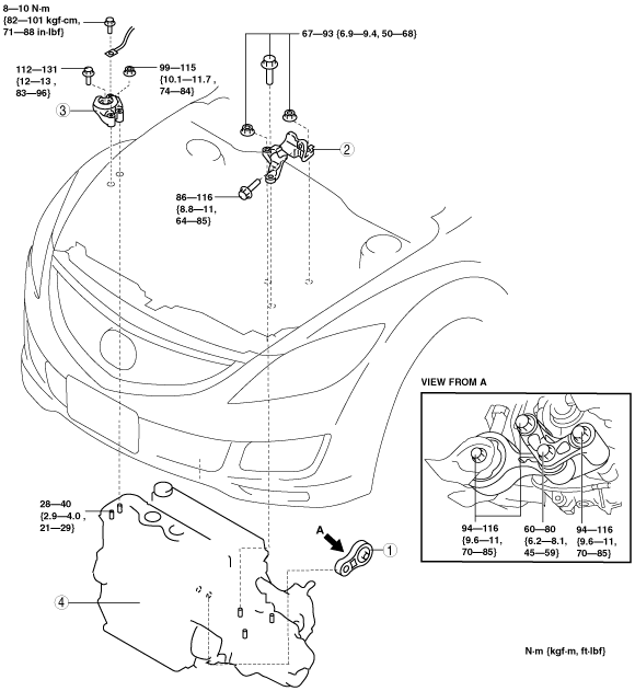
23. Remove in the order indicated in the table.
24. Install in the reverse order of removal.
25. Fill the engine coolant and transaxle oil.
26. Bleed the air from the fuel line. (See AFTER SERVICE PRECAUTION [MZR-CD (RF Turbo)].)
27. Start the engine and:
28. Perform a road test.
29. Reinspect the engine oil, engine coolant, transaxle oil.
am6zzw00003835
|
|
1
|
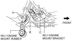
No.1 engine mount rubber
|
|
2
|
No.4 Engine mount bracket
|
|
3
|
No.3 Engine mount bracket
|
|
4
|
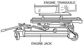
Engine, transaxle
|
No.1 Engine Mount Removal Note
No.3 Engine Mount Bracket, No.4 Engine Bracket Removal Note
1. Secure the engine and transaxle using an engine jack.
am5ezw00000575
|
Engine Mount Istallation Note
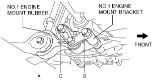
1. Install the through bolt A on the front crossmember side until approximately three pitches are showing.
2. Temporarily tighten bolts B and C.
am6zzw00003684
|
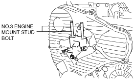
3. Tighten the No. 3 engine mount stud bolts.
am6zzw00003689
|
4. Secure the engine and transaxle using an engine jack.
am5ezw00000575
|
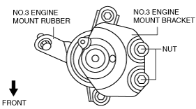
5. Temporarily the No.3 engine mount bracket nuts in the figure.
am6zzw00003147
|
6. Tighten the No.3 engine mount bracket bolt and nuts in the order shown in the figure.
am6zzw00003139
|
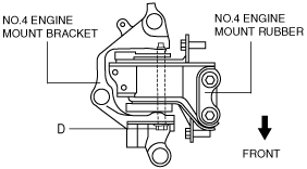
7. Align the No.4 engine mount bracket installation hole to the No.4 engine mount rubber on the body and temporarily tighten bolt D.
am6zzw00003196
|
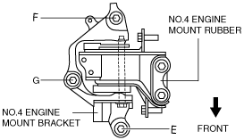
8. Temporarily tighten bolt E, and then the nuts in the order of F, G.
am6zzw00003144
|
9. Tighten bolt E, and then the nuts in the order of F, G.
10. Tighten the bolt D.
am6zzw00003143
|
11. Tighten the bolt H.
am6zzw00003692
|
12. Tighten the bolts in the order of B and C.
am6zzw00003685
|
13. Tighten the bolt A.